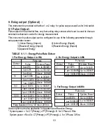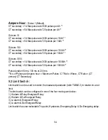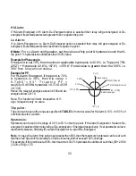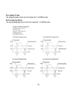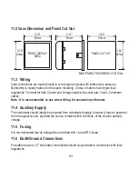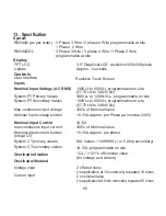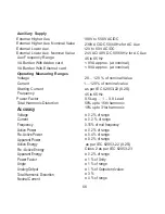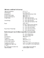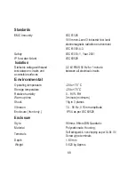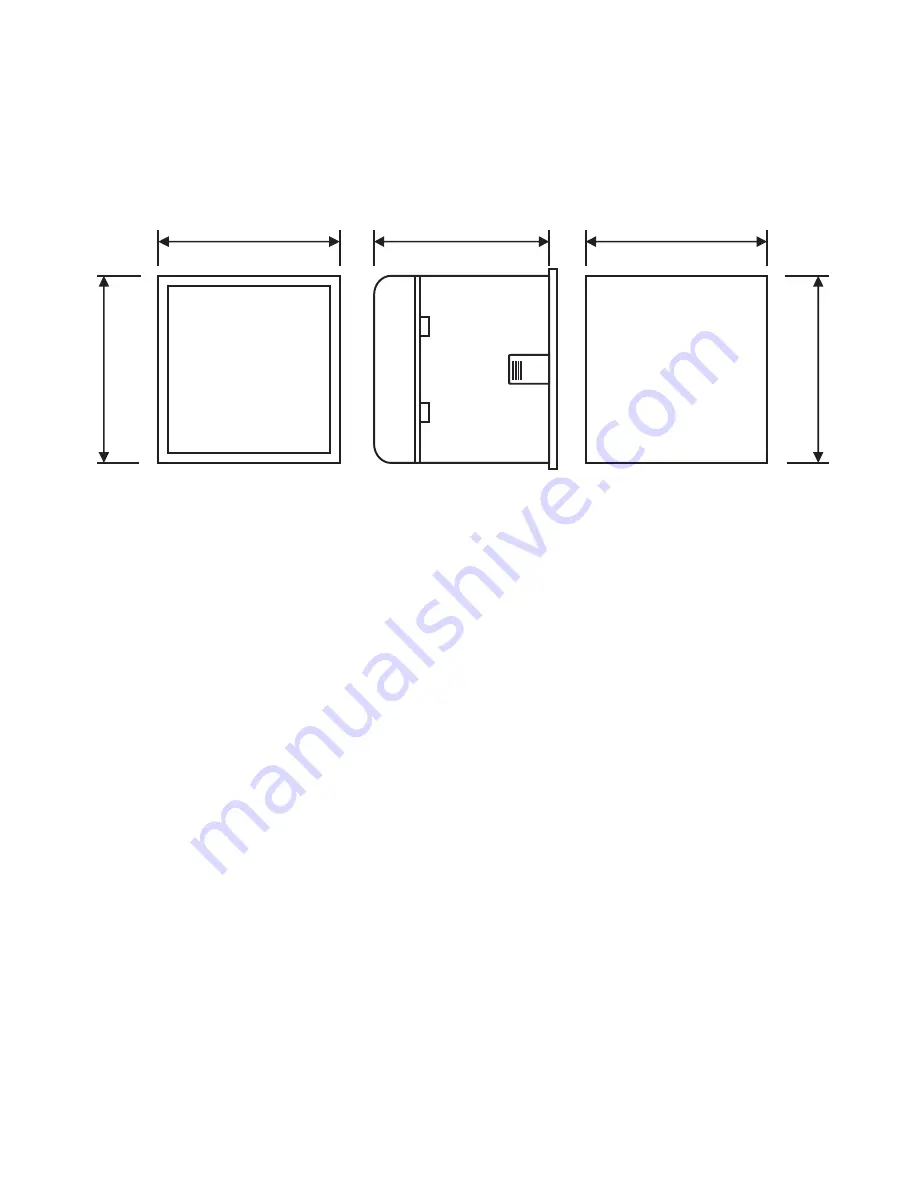
11.2 Case Dimension and Panel Cut Out
3.78”
96mm
FRONT DISPLAY
AREA
3.78”
96mm
3.15”
80mm
3.62”
92mm
PANEL CUTOUT
3.62”
92mm
MAX PANEL THICKNESS 0.18”,5mm
11.3 Wiring
Input connections are made directly to screw-type terminals with indirect wire pressure.
Numbering is clearly marked in the plastic moulding. Choice of cable should meet local
regulations. Terminal for both Current and Voltage inputs will accept upto 3mm x 2 diameter
cables.
Note : It is recommended to use wire with lug for connection with meter.
2
11.4 Auxiliary Supply
The
should ideally be powered from a dedicated supply, however it may be
instrument
powered
from the signal source, provided the source remains within the limits of the chosen auxiliary
voltage.
11.5 Fusing
It is recommended that all voltage lines are tted with 1 amp HRC fuses.
11.6 Earth/Ground Connections
For safety reasons, CT secondary connections should be grounded in accordance with local
regulations.
63
Summary of Contents for Master 3440iDL 0.2SS
Page 2: ......

