background image

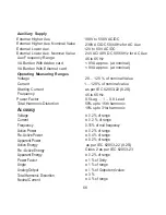
Nominal range of use of inuence quantities for measurands

50 .. 120 % of Rated Value
10 .. 120 % of Rated Value
Rated Value + 10 %

0

0 to 50  C

Voltage
Current
Input frequency 
Temperature

Auxiliary supply voltage

Auxiliary supply frequency

Rated Value + 10 %

Rated Value + 10 %

Temperature Coefcient

0

0.025% /  C for Voltage (50..120% of Rated Value)  

(For Rated value range of use                        

0

0.05% /  C for Current ( 10..120% of Rated Value )  

0

0... 50 C )                         

Error change due to variation of an 
inuence quantity

2 * Error allowed for the reference
condition applied in the test.

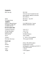
Reference conditions for Accuracy : 

0

0

23  C + 2  C
50 or 60Hz  ± 2%

Reference temperature
Input frequency 

Sinusoidal (distortion factor 0.005)

Input waveform

Rated Value + 1 %

Auxiliary supply voltage
Auxiliary supply frequency

Rated Value + 1 %

Voltage Range

50... 100% of Nominal Value.
60... 100% of Nominal Value for THD.

Current Range

10... 100% of Nominal Value.

Power 

cosØ / sinØ = 1 

10... 100% of Nominal Current &
50... 100% of Nominal Voltage.

For Active / Reactive Power & Energy

20... 100% of Nominal Value for THD.

Power Factor / Phase Angle

40... 100% of Nominal Current &
50... 100% of Nominal Voltage.

67

Summary of Contents for Master 3440iDL 0.2SS

Page 1: ...RISH Master 3440i 3440iDL 0 2S RISH Master 3440i 3440iDL 0 2S Operating Manual as per IEC62053 22...

Page 2: ......

Page 3: ...ial transformer Primary value 3 2 1 3 Potential transformer secondary value 3 2 1 4 Current transformer Primary value 3 2 1 5 Current transformer Secondary value 3 2 1 7 Demand integration time 3 2 1...

Page 4: ...delay time 3 2 4 1 2 9 De energizing delay time 3 2 4 Output Option selection screen menu 3 2 3 1 Resetting Parameter 3 2 3 Reset Parameter selection screen 3 2 2 Communication Parameter selection sc...

Page 5: ...1 Event Based Datalog 3 2 5 2 1 Status 3 2 5 Datalogging Option Selection 3 2 5 2 Time Based Datalog 3 2 5 3 Load Pro le Datalog 3 2 5 2 2 Time Interval 3 2 5 2 3 Parameters 3 2 6 1 Sag Threshold 3 2...

Page 6: ...ction Diagrams 14 Connection for Optional Pulse output RS 485 Analog Output Ethernet 10 Phasor Diagram Relay Output 9 Pulse output 9 1 Limit switch 9 2 7 Analog Output 6 3 Number of Interruption 6 2 O...

Page 7: ...3W or 3 Phase 4W system The front panel has a 3 5 Touch Screen through which the user can move across the available measurement readings reset the energy Min Max System Voltage and System Current and...

Page 8: ...rgy 8 Digit resolution Active Power System Phase 4 wire only Reactive Power System Phase 4 wire only Apparent Power System Phase 4 wire only Power Factor System Phase 4 wire only Phase Angle Phase 4 w...

Page 9: ...of Interruptions Phase Reversal Indication 4 wire only KW KW Amps KVA KW KW KW KW KW KW Hours Hours Counts Amps Current Demand KVA Demand KVA I1 THD I2 THD V1 THD V2 THD V3 THD I3 THD System Voltage T...

Page 10: ...TAGE SYSTEM Max VOLTAGE PHASOR RUN HOUR A A SYSTEM PARAMETERS And CURRENT Min VOLTAGE And CURRENT ON HOUR No OF INTERRUPTIONS CT SECONDARY DEMAND AUTO SCROLL Sec 3 2 1 5 Sec 3 2 1 7 INTEGRATION TIME P...

Page 11: ...utral OPTIONS Sec 3 2 4 POWER CHANGE PASSWORD Sec 3 1 ENERGY A A B B LINE CURRENT THD DIAGRAM Line to Line VOLTAGE Line to Neutral VOLTAGE NOTE 1 SCREENS MARKED WITH ARE AVAILABLE ONLY IN 4W SYSTEM NO...

Page 12: ...ERGY ON RESET COUNT Sec 3 2 1 12 ENERGY DIGIT RGB COLOR CODE Sec 3 2 9 Sec 3 2 4 2 RELAY OUTPUT 2 ANALOG OUTPUT 2 Sec 3 2 4 4 Acc To Table 7 1 A C POWER QUALITY SETTINGS Sec 3 2 6 DATALOG OPTIONS Sec...

Page 13: ...Sec 3 2 4 1 2 4 En De En Sec 3 2 4 1 3 RTC OUTPUT Sec 3 2 4 1 4 TIMER OUTPUT CONFIGURATION SELECTION Sec 3 2 4 1 3 2 ON DELAY Sec 3 2 4 1 3 3 OFF DELAY 1 to 9999 s Sec 3 2 4 1 3 4 En De En Sec 3 2 4 1...

Page 14: ...ntering the password very similar to any calculator in touchscreen mobile Enter Password is displayed on screen at start so that user can enter password using displayed keypad Touching key will displa...

Page 15: ...SWORD ACCEPTED is displayed now user can enter the new 4 digit password After entering new password user needs to touch key to con rm After con rming PASSWORD CHANGED is displayed on screen which ensu...

Page 16: ...SYSTEM TYPE 3 2 1 2 PT PRIMARY 3 2 1 3 PT SECONDARY 3 2 1 4 CT PRIMARY 3 2 1 5 CT SECONDARY 3 2 1 7 DEMAND INTEGRATION TIME 3 2 1 8 AUTO SCROLL 3 2 1 9 LOW CURRENT NOISE CUTOFF 3 2 3 RESET PARAMETERS...

Page 17: ...PT primary setting value is 100V L L to 692 8KV L L If value outside the range is entered It will display INVALID VALUE followed by correct range of parameter Note Changing PT Primary would erase the...

Page 18: ...to set value of PT Secondary user can con rm this value with a simple touch on key ENTER 3 2 1 4 Current Transformer Primary Value The nominal Full Scale Current that will be displayed as the Line cu...

Page 19: ...fers to 120 of nominal current and 120 of nominal voltage i e 462 96 MVA nominal power per phase Valid range of CT primary setting value is from 1 to 9999 If value outside the range is entered It will...

Page 20: ...L2 0 000 0 000 CT SECONDARY 5 AMPERE 1 AMPERE LINE NEUTRAL VOLTAGE VL2 VL2 VL2 0 000 0 000 LINE NEUTRAL VOLTAGE VL2 VL2 VL2 0 000 0 000 LINE NEUTRAL VOLTAGE VL2 VL2 VL2 0 000 0 000 DEMAND INTEGRATION...

Page 21: ...NEUTRAL VOLTAGE VL2 VL2 VL2 LINE NEUTRAL VOLTAGE VL2 VL2 VL2 CT SECONDARY 5 AMPERE 1 AMPERE LINE NEUTRAL VOLTAGE VL2 VL2 VL2 LINE NEUTRAL VOLTAGE VL2 VL2 VL2 LINE NEUTRAL VOLTAGE VL2 VL2 VL2 LOW CURRE...

Page 22: ...INE NEUTRAL VOLTAGE VL2 VL2 VL2 LINE NEUTRAL VOLTAGE VL2 VL2 VL2 ENERGY DIGIT RESET COUNT 7 DIGITS 9 DIGITS 8 DIGITS OK BACK 3 2 1 14 Meter Version 3 2 1 13 Energy Update Rate This screen allows user...

Page 23: ...s is 1 to 247 If value outside the range is entered it will display INVALID VALUE followed by the correct range of parameter 3 2 2 1 3 RS485 PARITY 3 2 2 1 1 RS485 ADDRESS 3 2 2 1 2 RS485 BAUD RATE 3...

Page 24: ...BIT NO PARITY WITH ONE STOP BIT NO PARITY WITH TWO STOP BITS EVEN PARITY WITH ONE STOP BIT are displayed on screen Touching radio buttion in front of particular option will select that option Touch on...

Page 25: ...Gateway value for each octet i e 0 to 255 Any value other than these would be indicated red and the previous value will get restored The user can con rm the setting by touching the key and cancel the...

Page 26: ...Touching Up key scrolls list in downward direction User needs to touch on the speci c parameter to be reset 3 2 3 Reset Parameter Selection Touching on any parameter will display the con rmation dial...

Page 27: ...Output Options screen 3 2 4 1 1 Pulse output After entering in the PULSE OUTPUT List of following parameters will be displayed 3 2 4 1 1 1 ENERGY 3 2 4 1 1 2 PULSE DURATION 3 2 4 1 1 3 PULSE RATE Thes...

Page 28: ...lar value will select that value Touch on key will con rm the setting Touching the key will keep the old selected setting and will return to previous menu Pulse rate divisor is set to 1 when Energy on...

Page 29: ...yed 3 2 4 1 2 1 LIMIT OUTPUT PARAMETER 3 2 4 1 2 2 ENERGY COUNT CONFIG 3 2 4 1 2 3 ENERGY TRIP POINT 3 2 4 1 2 4 ENERGY COUNT ON DELAY 3 2 4 1 2 5 PARAMETER CONFIG 3 2 4 1 2 6 TRIP POINT 3 2 4 1 2 1 L...

Page 30: ...set is 1077 then the relay will trip after x sec of the moment the value of the parameter becomes 1965 1077 888 where x is the ON Delay see Section 3 2 4 1 2 4 Caution Once the relay has tripped then...

Page 31: ...ON DELAY LINE NEUTRAL VOLTAGE VL2 VL2 VL2 LINE NEUTRAL VOLTAGE VL2 VL2 VL2 LINE NEUTRAL VOLTAGE VL2 VL2 VL2 CT SECONDARY 5 AMPERE 1 AMPERE LINE NEUTRAL VOLTAGE VL2 VL2 VL2 LINE NEUTRAL VOLTAGE VL2 VL...

Page 32: ...alue outside the range is entered it will display INVALID VALUE followed by correct range of parameter For details refer to section 9 2 3 2 4 1 2 8 Energizing Delay This screen allows the user to set...

Page 33: ...GIZING DELAY ENTER BACK 3 2 4 1 3 Timer Output After entering in the TIMER OUTPUT List of following parameters will be displayed 3 2 4 1 3 1 NUMBER OF CYCLES 3 2 4 1 3 2 TIMER CONFIGURATION 3 2 4 1 3...

Page 34: ...NERGIZED RELAY De energize on start Touch on key will con rm the setting and take back to the previous screen Touch on key will take back to the previous screen 3 2 4 1 3 3 On Delay LINE NEUTRAL VOLTA...

Page 35: ...on rm the setting and take back to the previous screen Touch on key will take back to the previous screen 3 2 4 1 4 RTC Output After entering in the RTC OUTPUT List of following parameters will be dis...

Page 36: ...ut keypad is provided to set the On Time user can confirm this value with a simple touch on key and cancel the change by touching the key The valid range for hour is 0 to 23 and that for minute is 0 t...

Page 37: ...list of parameters Refer TABLE 2 Parameter for Analog Limit output Touch on key will con rm the setting Touching the key will keep the old selected setting and will return to previous menu BACK OK OK...

Page 38: ...D DATALOG 3 2 5 2 TIME BASED DATALOG 3 2 5 3 LOAD PROFILE DATALOG Any of these can be selected for logging of data LINE NEUTRAL VOLTAGE LINE NEUTRAL VOLTAGE LINE NEUTRAL VOLTAGE CT SECONDARY LINE NEUT...

Page 39: ...ime interval between two successive time datalog entries Here 0 to 9 digit input keypad is provided to set the Time Interval user can confirm this value with a simple touch on key and cancel the chang...

Page 40: ...creen Section 3 2 5 2 for PARAMETERS setting option Only these selected parameters will get logged 3 2 5 3 Load Profile Datalog Setup Touching the LOAD PROFILE DATALOG option of Section 3 2 5 will pro...

Page 41: ...to 90 of nominal voltage If value outside this range is entered it will display INVALID VALUE followed by correct range of parameter ENTER BACK ENTER SAG THRESHOLD IN SAG THRESHOLD 0 3 2 6 2 Swell Thr...

Page 42: ...er can confirm this value with a simple touch on key and cancel the change by touching the key The valid range is 110 to 150 of nominal current If value outside this range is entered it will display I...

Page 43: ...DATE AND TIME SETUP 0 DATE AND TIME SETUP 2000 DATE YEAR 01 MONTH 01 HOUR 11 MINUTE 10 3 2 6 5 Overcurrent Hysteresis Setting Here 0 to 9 digit input keypad is provided to set the Overcurrent Hysteres...

Page 44: ...parameters of all three phases Different colors can be assigned to each phase using combination of Red Green and Blue component values L1 L2 L3 will be set to the assigned color To set these values t...

Page 45: ...28 130 Standard color combinations COLOR R G B Brass Blue Brown Black Bronze Copper Dark Blue Dark Brown Dark Green 0 51 102 66 33 0 0 140 184 115 51 166 41 41 204 128 51 181 166 66 0 0 255 0 0 0 33 3...

Page 46: ...0 0 000 0 000 LINE NEUTRAL VOLTAGE VOLTAGE MAIN VL2 VL2 VL2 VL2 V V V V V 0 000 0 000 0 000 LINE NEUTRAL VOLTAGE VOLTAGE MAIN VL2 VL2 VL2 V V V V V 0 000 0 000 0 000 Hold the lled circle LINE NEUTRAL...

Page 47: ...ion message would be shown the user will be asked to recalibrate the touch screen In such case the meter will retain the previously stored touch screen calibration values unless a successful calibrati...

Page 48: ...of times the Axillary Supply was Interrupted Even if the Auxiliary supply is interrupted count will be maintained in internal memory To reset No of Interruption manually see section Resetting Paramet...

Page 49: ...ts internally powered The output signals are present on pins A1 Analog Output 1 A2 Analog Output 2 These outputs can be individually assigned to represent any one of the measured and displayed Paramet...

Page 50: ...Nom 3 10 120 10 120 10 120 10 120 10 120 10 120 10 120 10 120 10 120 10 120 10 120 10 120 10 120 10 120 10 120 10 90 10 90 10 90 10 90 10 90 10 90 10 120 10 120 10 120 10 120 10 120 10 90 10 90 10 90...

Page 51: ...Inom Inom Vnom L L Vnom L L Vnom L L Inom 10 9999999 10 9999999 10 9999999 10 9999999 10 120 10 120 10 120 10 120 10 120 10 120 10 120 10 120 10 120 10 120 10 120 10 120 10 120 10 120 10 120 10 120 1...

Page 52: ...N AT L2 MIN AT L3 Event s Start Event s End 188 9 No Event 187 2 V V V Started at 12 08 2018 14 23 54 for 0 100 seconds Date Time of event DD MM YY HH MM SS Duration of event Shows POWERFAIL when mete...

Page 53: ...ry value in case of 3P3W system and L N PT Primary value in case of 3P4W and 1P2W system 3 The nominal current is taken to be CT Primary value 4 In case of polyphase systems sag begins when the voltag...

Page 54: ...or I time 0 Nominal value Threshold value Event Start Event End Event Duration Figure 9 2 Waveform of SWELL OVERCURRENT detection for 1P2W system Threshold Hysteresis value Example for swell overcurr...

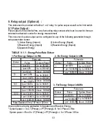
Page 55: ...ergy Output in Wh Divisor 1 Pulse rate Pulse System Power 1 per kWh 1 per 1000kWh 1 per 1000MWh Up to 3600W Up to 3600kW Above 3600kW 2 For Energy Output in kWh Divisor 1 Pulse rate Pulse System Power...

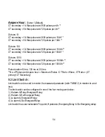
Page 56: ...3600 pulses per 1000Ah CT secondary 5A Max pulse rate 720 pulses per 1000Ah Pulse duration 60 ms 100 ms or 200 ms No of Pulses per Ampere hour Maximum Pulses CT Ratio Where CT Ratio CT primary CT Seco...

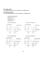
Page 57: ...ll work irrespective of sign It depends only on value Trip point can be set in the range as specified in TABLE 3 of nominal value for Hi Alarm 10 to 100 of nominalvalueforLo Alarm Trip point Examplefo...

Page 58: ...Hysterisis point Energizing Delay The energizing delay can be set in the range from 1 to 9999 seconds De Energizing Delay The De energizing delay can be set in the range from 1 to 9999 seconds 56...

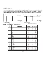
Page 59: ...y energised Relay de energised time De energized configuration on delay off delay repeat N times Relay energised Relay de energised time Energized configuration Timer output can be used to operate the...

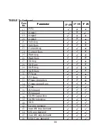
Page 60: ...m Phase Angle Avg Phase Angle Sum Freq Wh import Wh export VARh Capacitive VARh Inductive VAh kw imp demand max kW imp demand kW exp demand max kW exp demand kVAr Cap demand 17 18 19 20 21 22 23 24 25...

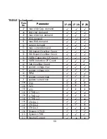
Page 61: ...demand KVA demand max KVA demand current demand max current demand Wh Import Overflow Count Wh Export Overflow Count VARh Capacitive OF Count VARh Inductive OF Count Vah Overflow Count system voltage...

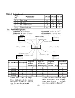
Page 62: ...r P Sign of Active Power Q Sign of Reactive Factor PF Sign of Power Inductive Capacitive Import 1 P Q L Import 4 P Q C Export 2 P Q C Export 3 P Q L Inductive means Current lags Voltage When Multifunc...

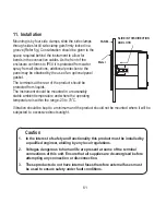
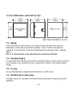
Page 63: ...ounted in a reasonably stable ambient temperature and where the operating temperature is within the range 20 to 70 C SLIDE IN THIS DIRECTION AND LOCK PANEL Meter Caution 1 In the interest of safety an...

Page 64: ...e a disturbance in function 2 Avoid routing leads alongside cables and products that are or could be a source of interference 4 ESD precautions must be taken at all times when handling this product 3...

Page 65: ...rrent and Voltage inputs will accept upto 3mm x 2 diameter cables Note It is recommended to use wire with lug for connection with meter 2 11 4 Auxiliary Supply The should ideally be powered from a ded...

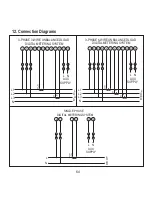
Page 66: ...EM P1 S1 P1 S1 L N AUX SUPPLY L1 L2 L3 N L O A D 2 5 8 3 4 6 7 9 3 PHASE 4 WIRE UNBALANCED LOAD DIGITAL METERING SYSTEM 2 5 8 11 1 3 4 6 7 9 13 14 L N AUX SUPPLY P1 S1 S1 P1 P1 S1 L1 L2 L3 N L O A D S...

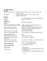
Page 67: ...rload Indication OL 121 of Nominal value for voltage and current 100VLL to 1200 kVLL programmable on site System CT primary values 2 x Rated Value 1s application at 10s intervals repeated 10 times 2 x...

Page 68: ...65 Hz External Higher Aux Nominal Value 230V AC DC 50 60 Hz for AC Aux as per IEC 62053 22 0 2S as per IEC 62053 22 0 2S Accuracy 0 2 of range 0 2 of range Frequency 0 15 of mid frequency Active Ener...

Page 69: ...f an in uence quantity 2 Error allowed for the reference condition applied in the test Reference conditions for Accuracy 0 0 23 C 2 C 50 or 60Hz 2 Reference temperature Input frequency Sinusoidal dist...

Page 70: ...and test between circuits and accessible surfaces Environmental 0 20 to 70 C 0 25 to 75 C 0 90 RH 3 minute minimum 15g in 3 planes 10 55 Hz 0 15mm amplitude IP 54 as per IEC 60529 Operating temperatur...

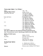
Page 71: ...p to 3600W 1 per 100kWh up to 3600kW 1 per 100MWh above 3600 kW 100 1 per 1000Wh up to 3600W 1 per 1000kWh up to 3600kW 1 per 1000MWh above 3600 kW 1000 60ms 100ms or 200ms Pulse Duration Note Above c...

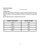
Page 72: ...rticular nominal power is set which indicates 1kWh energy Energy can be Watt VA or Var Following table shows impulses corresponding to nominal system energy Note ForExternalCToptionconsiderNominalcurr...

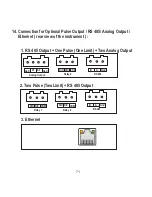
Page 73: ...Ethernet rear view of the instrument 1 RS 485 Output One Pulse One Limit Two Analog Output A1 A2 Gnd Analog Output N O N C COM Relay 2 B A Gnd RS 485 Gnd 2 Two Pulse Two Limit RS 485 Output N O N C C...

Page 74: ...only by installers trained to make electrical power installations and is intended to describe the correct method of installation It is the user s responsibility to determine the suitability of the in...

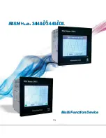
Page 75: ...Multi Function Device Multi Function Device RISH Master 3440i 3440iDL RISH Master 3440i 3440iDL 73...

Reviews: