8 - 0
CZ80 / CV860 Rev. .0
CHAPTER 8: PRINT DRUM
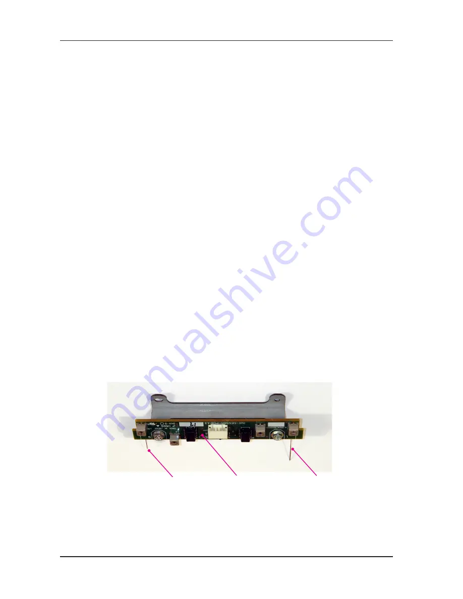
Ink sensor PCB
Overflow sensor
Ink sensor
8. Ink Sensor PCB
REMOVAL
) Remove the Drum out from the machine and pull out the ink bottle.
2) Remove the Drum cover. (M3x8 screws; 4 pcs)
3) Remove following parts.
Clamp plate base unit (M4x8 screws; 4 pcs)
Drum screen (M4x8 screws; 4 pcs)
Drum body (M4x8 screws; 6 pcs)
4) Unplug the Ink sensor wire harness connector.
5) Remove the Ink sensor assembly. (M3x8 screws; 2 pcs)
6) Remove the Ink sensor cover.
7) Remove the Ink sensor PCB. (M3x6 screws; 2 pcs)
Precaution in Assembly
1) The Ink sensor and Overflow sensor needles must be straight. Do not deform or bend the sensor
needles.
2) If the needles are bent, straighten then out by hand before installing the Ink sensor PCB back on
the Drum.
3) The Clamp plate base assembly should be pushed towards the rear of the Drum, as there is a
small play in mounting the assembly.
Checks after Assembly
1) Make sure that the Ink sensor is not touching the Doctor roller or Driving shaft, as that would
cause the Ink sensor to make false detection.
2) In normal condition, the tip of the Ink sensor should be 5mm plus/minus 0.5mm from the outer
surface of the Driven shaft. The tip of the Overflow sensor should be 10mm plus/minus 1mm
from the outer surface of the Driving shaft.
* As shown on the photograph, the Ink sensor and Overflow sensor should be 90 degrees against the
Ink sensor PCB.
RISO Inc. Technical Services & Support
US.RISO.COM


