16 - 1
CZ180 / CV1860 Rev. 1.0
CHAPTER 16: WIRING DIAGRAMS
CHAPTER
16
: WIRING DIAGRAMS
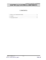
CONTENTS
1. Power Supply PCB (PHOTOGRAPH) ....................................................2
2. Mechanical Control PCB (PHOTOGRAPH) ............................................3
3. Connection between PCBs .....................................................................4
4. Power Supply ..........................................................................................5
5. Main Components Area ..........................................................................6
6. CN8 and CN12 of Mechanical Control PCB ...........................................7
7. Print Drum Area ......................................................................................8
8. Master Making Area ................................................................................9
9. Master Removal Area ...........................................................................10
10. Paper Ejection Area ..............................................................................11
11. Operation Panel Area ...........................................................................12
12. Options .................................................................................................13
13. Fuses ....................................................................................................14
RISO Inc. Technical Services & Support
US.RISO.COM


