16 - 5
CZ180 / CV1860 Rev. 1.0
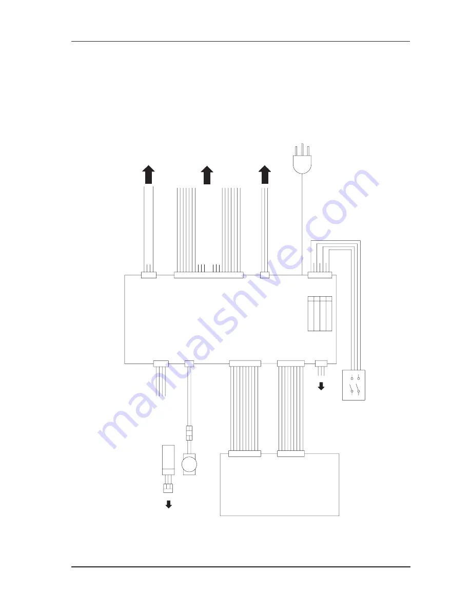
CHAPTER 16: WIRING DIAGRAMS
4. Power Supply
CN2
XR10P-Y
01
02
03
04
05
06
07
08
DA LAT
/POWER FAI
L
GND
/24V-ON
/TPH_CTL
DA CL
K
SLEE
P
DA DAT
02
07
08
05
06
03
04
01
CN4
CZ10P-Y
MECHANICAL CONTROL
PCB
CN1
3
24V-B
24V-A
5V
5V
VH9P
GND
02
07
08
05
06
03
04
CN1
01
POWER SUPPL
Y
PCB
PS15-N200
023-50073
(Power: 200V)
03
01
02
CN4
XH3P
for TPH Power Adjustmen
t
07
08
03
05
06
04
01
02
GND
-S
12
16
15
14
13
10
11
09
20
19
18
17
GND GND GND GND GND
Vh Vh Vh Vh Vh Vh +S
CN5
Diagram: 042-50000-03
(TPH Power)
CN9
02
01
+5.1
V
GND
04
07
06
05
02
03
01
CN6
MAIN SWITCH
1
3
2
4
Option Wire Harness 042-53011
DF1B20P
VH7P
Mechanical Control PCB Power Wire Harness 042-53014
Power Supply Switch
04
07
08
06
05
02
03
01
PW
M
GND
10
09
24V-O
P
09
09
VH9P
10
09
M-OUT(-)
M-OUT(+
)
01
02
Main Motor
GND
GND
+24V-
A
+5.1V
03
04
02
01
Image Control PCB Power (not used)
N.
C
Main Motor Relay Drive
Main Motor Relay 24V
N.
C
01
02
03
04
Diagram: 042-50000-07
(Mechanical Control PCB CN19)
CN3
CN8
CN7
PF
03
VH3P
XR4P-Y
VH4P
VL2P
+S N.
C
-S
GND
PGND
PGND
DC
POWER CORD (C
)
488-00049
GND
OUT
VC
C
Photo Interrupt
Type
Diagram: 042-50000-07
(Mechanical Control PCB CN6
)
02
01
03
Main Motor FG Sensor
XR3P-
Y
01
04
03
02
CN6 power supply pin
AC(L)-SW-OUT
AC(N)-SW-OUT
AC(N)-SW-IN
AC(L)-SW-IN
7
5
3
1
N.C
N.C
N.C
Power Supply Switch Wire Harness 042-53009
Main Motor Wire Harness 042-53010
Diagram: 042-50000-10
(Option Power Supply
)
N.C
N.C
N.C
N.C
N.C N.C
Interlock Wire Harness 042-53008
Master Making Unit Wire Harness 042-28057
02
VL2P
01
01
02
03
02
14
12
13
11
07
09
10
08
06
05
04
03
01
18
15
01
02
blue red
CT3P Relay Connector
03
02
01
Bottom Rear Wire Harness 042-53004
POWER CORD (E
)
488-00048
Power Supply Area
Mechanical Control PCB Power Wire Harness 042-53014
RISO Inc. Technical Services & Support
US.RISO.COM


