4 - 7
CZ80 / CV860 Rev. .0
CHAPTER 4: FIRST PAPER FEED
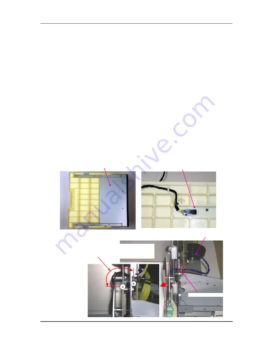
Paper detection sensor
Paper feed table cover
3. Removal of Paper detection sensor
Removal
) Lower the Paper feed tray all the way down, pull Print drum out and switch OFF machine power.
2) Detach the following parts.
Front cover (M3x8 screws; 6 pcs)
Paper feed tray unit (6mm E-ring; 2 pcs)
3) Remove the mounting screws from the Paper feed tray cover and remove the cover. (M3x6
screws; 6 pcs & M3x8 screws; 2 pcs)
4) Detach the Paper detection sensor by gently widening the plastic mounting hook and
disconnecting the wire harness connector.
Precaution in Assembly
1) Fit the Paper detection sensor firmly between the mounting hooks.
2) Match the positioning pins and positioning holes when attaching the Paper feed tray cover.
3) Wire the Paper detection sensor wire harness in correct path and make sure to attach new wire
band in the original position.
4) Firmly attach the wire harness of the Paper detection sensor onto the Elevator spring bracket (front)
using a wire band.
When tying the wire band, make sure that the length of the wire harness between A and B (refer
to the photo) is not too long and not too short. The wire should be between 60mm to 53mm in
length between A and B. This is to prevent the wire harness from touching the paper or giving too
much tension on the wire harness.
Wire harness band 00mm
Paper detection sensor wire harness
Mount wire band so the distance of the wire harness
from A to B is between 60mm to 53mm.
RISO Inc. Technical Services & Support
US.RISO.COM


