background image

Fenwal Thermostat 

– (Omni 3, Omni 5 & Omni 10) The adjustable range is from 0

o

. F (-18

o

 C) to 

100

o

 F (38

o

 C). Thermostat is not preset at factory. Fill the trough to proper water level. Check the 

water temperature with a thermometer. The next morning, check the water temperature again. If the 

water is warmer than desired, turn the thermostat down. If there is ice forming on the surface of the 

water, turn the thermostat up. Only slight adjustments should be made to the thermostat at any time. 

A 1/16 turn on the thermostat will change the water temp. 7

o

 F (4

o

  C). 44

o

F (7

C) in the trough 

represents the most economical operation. Counter clockwise raises the thermostat setting. 

M.

Disc Thermostat 

– (Omni 1, Omni 2 and Omni 2 SP) The disc thermostat is mounted

in a bracket under the trough, which allows it to be moved relative to the heater. To ease

movement of thermostat turn ¼  turn. To lock in position after adjustment turn ¼ turn

back. 

As the thermostat is moved toward the heater, the water temperature

in the trough is lowered

.

  The best location is determined by checking the trough

temperature several times during the heating season.

N.

Final Water Connection for Omni 1, Omni 2 and Omni 2 SP Only 

– Connect the

top of the supplied hose to the valve, cut hose to proper length and slip onto the barb

fitting of the valve assembly. Clamps and fittings are furnished to secure the connection. (This connection was

already made in step “H” for the Omni 3 & 5.)

O.

Seal the Base

 - After the unit is completely installed, apply a bead of caulking around the base of the fountain

to ensure no wind enters through the base of the unit.

NOTE:


Sealing the bottom of the unit from cold air is an important aspect of the unit's thermal 

performance.


P.

Drain Plug 

– Insert the drain plug firmly into the drain hole in the center of the trough.

Q.

Water Seal Drain 

– Install the small drain plug into the drain hole in the water seal groove around the valve

chamber seal. This plug may be removed during the non-freezing periods to allow the water seal groove to drain.

R.

Valve Frame and Cover

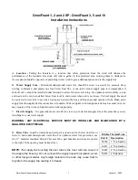
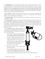
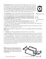
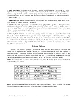
 – (OmniFount 3 & 5) Before installing the valve chamber frame, the weather seal

must be installed on the frame (see picture below).  The seal is installed by removing the paper backing from the

adhesive side and then starting at the midpoint of the frame leg;  attach the seal to the frame.  Work your way

around the frame with the seal as close to the inside edge as possible and then up the other leg to the halfway

point.  At this time cut any extra foam seal as needed then repeat for other side.  The frame can then be attached to

the casing using the screws and nuts provided in parts bag. A washer should be used on the head of the screw as

well as under the nut. Tighten securely.

NOTE: 

T

he foam seal must be placed on the 

omni 3 & 5 frame as shown in the picture to the 
right. The foam seal is to prevent cold air from 
leaking into the valve chamber and causing the 
valve to freeze.
 

OmniFount Series Instruction Manual

5

January 1, 2020

Summary of Contents for 16533

Page 1: ...fountain on the market This unit is built to give you excellent service when properly installed and maintained Please follow instructions carefully Read and understand all instructions before installing Ritchie Industries Inc 800 747 0222 www ritchiefount com Part 17835 January 1 2020 RitchieWaterers ...

Page 2: ...y line thoroughly before connection to fountain Water supplies with foreign material such as sand rust etc may require a filter to keep fountain valve working properly C Electric Supply It is generally most cost effective to run your electrical supply line at the same time you are trenching for your water supply WARNING ANY ELECTRICAL SERVICE MUST BE INSTALLED AND MAINTAINED BY A QUALIFIED ELECTRI...

Page 3: ...the OmniFount 5 10 have 6 molded hold down pockets The use of 3 8 x 5 stainless steel expansion anchor bolts not included is recommended Anchor bolts are available from Ritchie in a two pack part 16555 Large diameter fender washers are included and should be used with anchor bolt to prevent damage to the plastic casing Remove the side access panel to prepare for the remainder of the installation p...

Page 4: ...cal codes A means for disconnection must be incorporated in the fixed wiring in accordance with the wiring rules For wiring connections see wiring diagram Make connections according to the wiring diagram below WARNING DISCONNECT POWER IF THE WATER SUPPLY IS TO BE SHUT OFF FOR AN EXTENDED AMOUNT OF TIME FAILURE TO TURN OFF POWER CAN RESULT IN DAMAGE TO THE WATERING FOUNTAIN WARNING THIS INSTALLATIO...

Page 5: ...NG DIAGRAM 240V SINGLE PHASE WARNING Check the nameplate for your unit Only connect 120VAC to a 120V Unit WARNING Check the nameplate for your unit Only connect 230 240VAC to a 240V Unit OmniFount Series Instruction Manual 4 January 1 2020 ...

Page 6: ...n was already made in step H for the Omni 3 5 O Seal the Base After the unit is completely installed apply a bead of caulking around the base of the fountain to ensure no wind enters through the base of the unit NOTE Sealing the bottom of the unit from cold air is an important aspect of the unit s thermal performance P Drain Plug Insert the drain plug firmly into the drain hole in the center of th...

Page 7: ... and debris You can shut off the water with the shut off valve located under the unit or by holding the float in the up position After the water and debris has drained reinstall the plug and let the tank refill Now is a good time to readjust the float if needed Reinstall cover and you are done Ritchie Valves Ritchie valves come in various sizes and pressure ratings as shown below green for high su...

Page 8: ...18147 Access Panel Hardware pkg 1 pkg 21 18633 Plug 3 Water Channel 2 pkg 1 pkg 7 11885 Disc Thermostat pkg 1 pkg NS 13830 Cable Htr 120V 48W 1 pkg 1 pkg 8 18266 Frame Bolt nut wshr SS 3 pkg 1 pkg NS 16627 Omni 1 Accessory pkg 1 pkg 9 18655 Ritchie Decal 7 5 1 pkg 1 pkg NS 16523 Seal Foam 1 4 x3 4 x25 Roll 1 10 18628 Drain Plug 2 pkg 1 pkg NS 14866 Seal Foam 1 2 x3 4 x10 Roll 1 11 14150 Heater 120...

Page 9: ...6 18147 Access Panel Hardware pkg 1 pkg NS 13830 Cable Htr 120V 48W 1 pkg 1 pkg 7 11885 Disc Thermostat pkg 1 pkg NS 16627 Omni 2 Accessory pkg 1 pkg 8 18266 Frame Bolt nut wshr SS 3 pkg 1 pkg NS 16523 Seal Foam 1 4 x3 4 x25 Roll 1 9 18628 Drain Plug 2 pkg 1 pkg NS 14866 Seal Foam 1 2 x3 4 x10 Roll 1 10 14150 Heater 120V 125W 1 pkg 2 pkgs 11 18075 Drain Washer 6 pkg 1 pkg 12 11471 Drain Pipe with ...

Page 10: ... 1 6 18147 Access Panel Hardware pkg 1 pkg 21 18633 Plug 3 Water Channel 2 pkg 1 pkg 7 11885 Disc Thermostat pkg 1 pkg NS 13830 Cable Htr 120V 48W 1 pkg 1 pkg 8 18266 Frame Bolt nut wshr SS 3 pkg 1 pkg NS 16627 Omni 2 Accessory pkg 1 pkg 9 18653 Ritchie Decal 12 1 pkg 1 pkg NS 16523 Seal Foam 1 4 x3 4 x25 Roll 1 10 18628 Drain Plug 2 pkg 1 pkg NS 14866 Seal Foam 1 2 x3 4 x10 Roll 1 11 14150 Heater...

Page 11: ...hannel 2 pkg 1 pkg 7 16534 Fenwal Thermostat SS pkg 1 pkg NS 12583 Valve Supply Line pkg 1 pkg 18320 O Ring Fenwal 6 pkg 1 pkg NS 13830 Cable Htr 120V 48W 1 pkg 1 pkg 18074 Nut Brass Fenwal 6 pkg 1 pkg NS 16554 Omni 3 Accessory pkg 1 pkg 8 18319 Frame Bolt Wshr SS 2 pkg 1 pkg NS 16523 Seal Foam 1 4 x3 4 x25 Roll 1 9 18095 Trough Screw Nut SS 2 pkg 1 pkg NS 14866 Seal Foam 1 2 x3 4 x10 Roll 1 10 18...

Page 12: ...hannel 2 pkg 1 pkg 7 16534 Fenwal Thermostat SS pkg 1 pkg NS 12583 Valve Supply Line pkg 1 pkg 18320 O Ring Fenwal 6 pkg 1 pkg NS 13830 Cable Htr 120V 48W 1 pkg 1 pkg 18074 Nut Brass Fenwal 6 pkg 1 pkg NS 16554 Omni 5 Accessory pkg 1 pkg 8 18319 Frame Bolt Wshr SS 2 pkg 1 pkg NS 16523 Seal Foam 1 4 x3 4 x25 Roll 1 9 18095 Trough Screw Nut SS 2 pkg 1 pkg NS 14866 Seal Foam 1 2 x3 4 x10 Roll 1 10 18...

Page 13: ... 1 pkg 20 18633 Plug 3 Water Channel 2 pkg 1 pkg 7 16534 Fenwal Thermostat SS pkg 1 pkg NS 12583 Valve Supply Line pkg 1 pkg 18320 O Ring Fenwal 6 pkg 1 pkg NS 13830 Cable Htr 120V 48W 1 pkg 1 pkg 18074 Nut Brass Fenwal 6 pkg 1 pkg NS 16554 Omni 10 Accessory pkg 1 pkg 8 18471 Frame Bolt Wshr SS 4 pkg 1 pkg NS 16523 Seal Foam 1 4 x3 4 x25 Roll 1 9 18095 Trough Screw Nut SS 2 pkg 4 pkgs NS 14866 Sea...

Page 14: ...at riser tube is free of water and mud that may freeze Check that flexible hose does not touch side of casing or frame Check casing for air leaks Check for air gaps between casing and concrete floor Valve won t stop dripping Check float adjustment Check for waterlogged float or float rubbing on side of valve compartment Check for excessive system water pressure Disassemble valve and check for sand...

Page 15: ... rights which vary from state to state All warranty claims must be processed through an Authorized Ritchie Dealer Distributor Proof of purchase is required This warranty is not transferable The period of warranty begins at original date of purchase as follows Poly Units Base top and ball closures 10 year limited against manufacturing defect 100 first five years then declining 20 per year for the r...

Reviews: