background image

E.


Mounting Platform

 - A concrete platform must be provided for all fountains. Use a minimum of 4” thick, 

(6” recommended), large enough to accommodate fountain, and additional 4” step (on top of the platform) 

extending 18” out from each side of the unit. This will protect the unit from manure handling equipment, as well 

as discouraging animals from defecating in the fountain. Extending the platform provides animals a place to stand 

while drinking, consider the size of your animals when determining the dimensions of your platform. The 

concrete step and platform should slope away from the fountain for drainage. A rough broom finish to concrete 

surface provides better footing for livestock. 

F.


Hose Connection 

- Connect hose fitting to shut-off valve at top of concrete. Slip on barb fitting with 

furnished clamps. Hose should not touch insulation or outside surface of fountain. Place the hose under the 

fountain as you move the unit in place over the riser tube.


G.


Anchoring Fountain

 - Steel fountains are provided with four hold-downs to anchor your unit securely to the 

concrete. Screw the hold down angles on to the unit then anchor down the unit. Use of 3/8” x 3-1/2” stainless steel 

expansion anchor bolts (not included) is recommended for concrete installations. Anchor bolts are available from 

Ritchie in a two pack, part # 14261. Use an all-weather sealant under the outside edge when anchoring to concrete 

to keep air from leaking under fountain. 

H.


Final Water Connection

– Connect the top of the supplied hose to the valve, cut hose to proper length and 

slip onto the barb fitting of the valve assembly. Clamps and fittings are furnished to secure the connection.  

I.


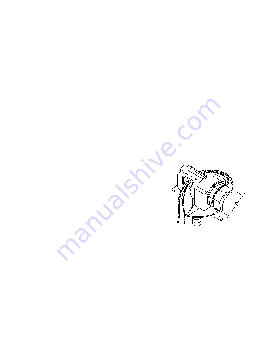
Cable Heater – 

Uncoil cable heater and loop around the valve. 

Attach the remaining part of the cable heater to the water supply, as 

far down the riser tube as possible, with the cable twist ties provided.  

(See drawing on previous page.) This heater is water tight, but should 

not be immersed in water.  

CAUTION: Installation must not cause any strain on heater 

wiring connections.  Do not cross the cable over itself along the 

water line. Avoid heater damage caused by hot spots due to its 

leads lying close to each other. Do not wrap additional 

insulation around heater. 

J.


Electrical Connection

 - The electrical installation should be made and maintained by a qualified electrician 

conforming to national and local codes. 

A means for disconnection must be incorporated in the fixed wiring in 

accordance with the wiring rules. A suitable fuse or circuit breaker with properly sized wire must protect the 3-wire power to 

the fountain. For wiring connections, see wiring diagram. Do not by-pass the terminal block to power unit.  Make 

connections according to the wiring diagram below. 

WARNING: DISCONNECT POWER IF THE WATER SUPPLY IS TO BE SHUT OFF FOR AN 

EXTENDED AMOUNT OF TIME.  FAILURE TO TURN OFF POWER CAN RESULT IN DAMAGE TO 

THE WATERING FOUNTAIN.


Cattle, Combination, and AC Series 

Fountains Installation Instructions

2

17 October, 2012

Summary of Contents for 1AC

Page 1: ...Congratulations you have just purchased the finest watering fountain on the market This unit is built to give you excellent service when properly installed and maintained Please follow instructions c...

Page 2: ...fore connection to fountain Water supplies with foreign material such as sand rust etc may require a filter to keep fountain valve working properly C Electric Supply It is usually most cost effective...

Page 3: ...concrete to keep air from leaking under fountain H Final Water Connection Connect the top of the supplied hose to the valve cut hose to proper length and slip onto the barb fitting of the valve assemb...

Page 4: ...t be made and maintained in strict conformity with National Local plumbing codes and National Local electrical codes CSA in Canada The applicable provisions of these codes take precedent Failure to ma...

Page 5: ...d If you are using solid wire then you will be able to just push the wire into the slot Stranded wire will require you to press the button down HEATER 240V FENWAL THERMOSTAT CABLE HEATER TERMINAL BLOC...

Page 6: ...nd fix any leaks Adjust float for a water depth of 2 inches below top of trough or overflow pipe by adjusting the thumbscrew or wing nut P Install Side Access Panel and Cover Once all water line conne...

Page 7: ...rmal service or handling and to any products altered or repaired with other than original equipment or manufacturer s parts This warranty gives you specific legal rights and you may also have other ri...

Page 8: ...of water and mud that may freeze Check that flexible hose does not touch side of casing or frame Check casing for air leaks Check for air gaps between casing and concrete floor Valve won t stop drippi...

Page 9: ...kg Optional 1 PKG 18320 O Ring Fenwal 6 pkg 1 pkg NS 12583 Valve Supply Line pkg 1 pkg 18074 Nut Brass Fenwal 6 pkg 1 pkg NS 13830 Cable Htr 120V 48W 1 pkg 1 pkg 8 15154 Screw 1 4 x5 8 TC SS 10 pkg 1...

Page 10: ...kg Optional 1 pkg 18320 O Ring Fenwal 6 pkg 1 pkg NS 12583 Valve Supply Line pkg 1 pkg 18074 Nut Brass Fenwal 6 pkg 1 pkg NS 13830 Cable Htr 120V 48W 1 pkg 1 pkg 8 15154 Screw 1 4 x5 8 TC SS 10 pkg 1...

Page 11: ...11515 Valve Bracket 1 2 w screws 1 pkg 9 18114 Trough Bolt Nut 5 pkg 1 pkg 28 12575 Red Valve 1 2 1 pkg 10 18628 Drain Plug 2 pkg 1 pkg 29 13613 Float with Short Arm 1 pkg 11 11419 Heater 120V 250W 1...

Page 12: ...Optional 1 pkg 7 11885 Disc Thermostat pkg 1 pkg NS 13830 Cable Htr 120V 48W 1 pkg 1 pkg 8 15158 J Bolt Nut ZP 10 pkg 1 pkg NS 18323 2AC Accessory pkg 1 pkg 9 17500 Drain Pipe Guard 1 NS 15652 2AC Ca...

Page 13: ...2 pkg Optional 1 pkg 7 11885 Disc Thermostat pkg 1 pkg NS 13830 Cable Htr 120V 48W 1 pkg 1 pkg 8 15158 J Bolt Nut ZP 10 pkg 1 pkg NS 18323 2AC Accessory pkg 1 pkg 9 17500 Drain Pipe Guard 1 NS 18059 2...

Page 14: ...Htr 120V 48W 1 pkg 1 pkg 7 11885 Disc Thermostat pkg 1 pkg NS 18323 1AC Accessory pkg 1 pkg 8 15158 J Bolt Nut ZP 10 pkg 1 pkg NS 15651 1AC Casing Insulation pkg 1 plg 10 18628 Drain Plug 2 pkg 1 pkg...

Page 15: ...Fountain Model Part Hole to Hole Location 3 Cattle Fountain 16743 15 1 2 x 30 5 Cattle Fountain 16745 18 1 8 x 38 1 2 3 Combination Fountain 16769 15 1 2 x 30 1 AC 18034 8 1 2 x 18 2 AC 18033 8 7 16...

Reviews: