


P
UB
. N
O
. GUARDRITE STRAP REV 3.1 - © JUNE 2013
5
GUARDRITE
®
STRAP SYSTEM BARRIER
NOTICES
GUARDRITE STRAP MODELS
The Guardrite STRAP is available in two different models: The standard model is capable of
stopping a 10,000 lb. fork truck moving at 4 mph. The light duty model is intended only to guide
and restrict pedestrians. See the note below for expected deflection distances to aid in
application.
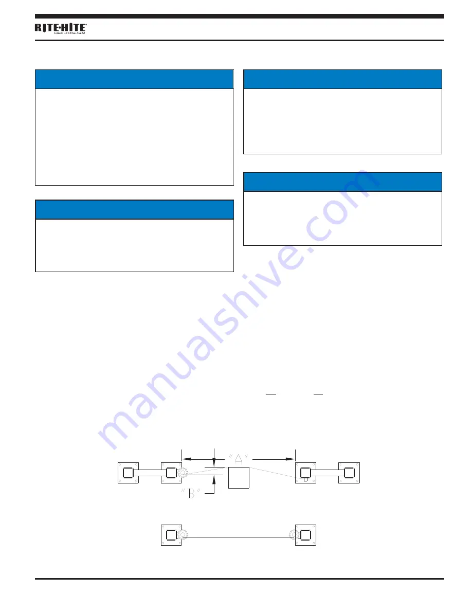
IMPORTANT
RESTRAINING STRAPS WILL DEFLECT
WHEN LOADED. USE CARE WHEN
DETERMINING MOUNTING LOCATION
NEAR EQUIPMENT OR CHANGE IN
ELEVATION. ALLOW FOR THE
FOLLOWING DEFLECTION DISTANCES:
"A" "B"
10 FT (3048 MM) 20 IN (508 MM)
20 FT (6096 MM) 32 IN (813 MM)
30 FT (9144 MM) 42 IN (1067 MM)
40 FT (12192 MM) 50 IN (1270 MM)
50 FT (15240 MM) 65 IN (1651 MM)
60 FT (18288 MM) 84 IN (2134 MM)
EXPECTED DEFLECTION
FORK TRUCK BARRIER (DOUBLE POSTS)
PEDESTRIAN BARRIER ONLY (SINGLE POSTS)
10,000 LBS
MOVING
AT 4 MPH.
Figure 2
NOTICE
To be properly positioned, the straps must be
fully horizontal with all slack removed. The
lock pin must be fully inserted through the
tensioner into the tensioner bracket, and there
must be a minimum of 1-1/2 full rotations of
strap wrapped around the tensioner. If any
one of the above conditions is not met, you
must retension the System Barrier.
NOTICE
The barrier straps should be inspected on a
regular basis. They should be replaced when
there are signs of wear. Stretching, snags,
fraying and punctures are all indications that
the straps should be replaced.
NOTICE
SHORTENING OF STRAPS.
If you need to
shorten the strap length, cut the strap using a
sharp scissors and melt the end to prevent
fraying.
NOTICE
The storage system is not intended to be
used when tensioning the straps. This will
make the tensioning of the straps more
difficult. Please refer to the operational video.


