


P
UB
. N
O
. GUARDRITE STRAP REV 3.1 - © JUNE 2013
7
GUARDRITE
®
STRAP SYSTEM BARRIER
STORAGE SYSTEM INSTALLATION
The storage system is used to neatly organize
and store the straps when the system is not in
use. The storage system is intended to be
installed on the non-traffic side of the post to
keep the straps out of the way and to protect
the storage device from incidental contact.
Use the ½" x 6.5" bolts and lock nuts provided
to attach this system to the face of the post
adjacent to the tensioner brackets. Note that the
holes in the brackets are offset to allow these
brackets to align with the tensioner brackets.
Insert the storage rod down through the storage
brackets. Using the #10 x 2.25" bolts and nuts
provided, attach the pressure straps to the
storage rod. Do not tighten hardware at this
time. One pressure strap should get attached
for each strap that will be rolled up.
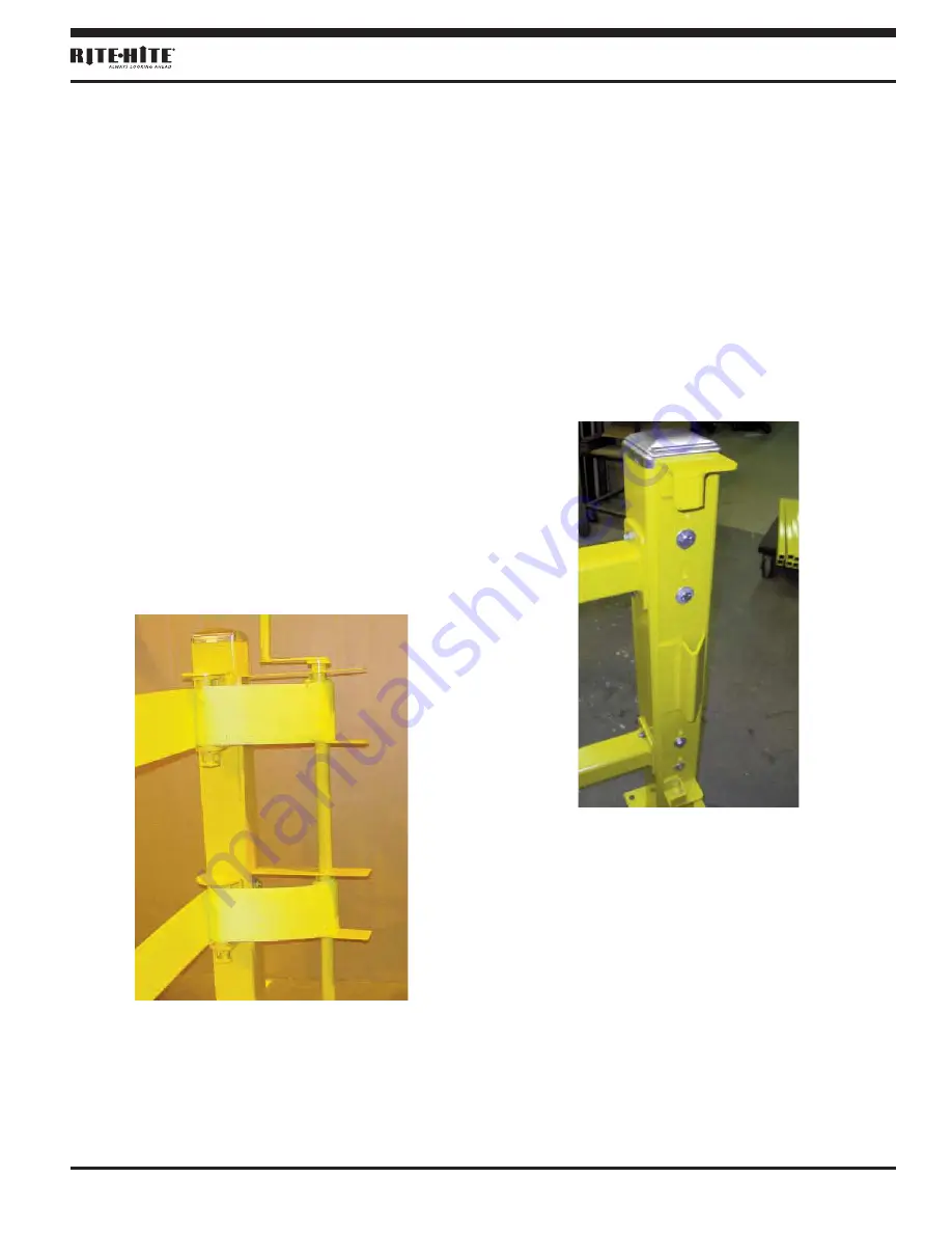
LATCH BRACKET INSTALLATION
Position the latch bracket on the post so that
the top of the latch bracket is aligned with the
top of the post. Fasten the bracket to the post
with the (4) ½" x 6.5" bolts, washers, and lock
nuts that are provided.
Before the fasteners are tightened, install the
post cap on the post. If the post cap is not
installed before the latch plate is tightened, the
latch plate will interfere with the post cap
installation.
POST POSITIONING
Position the posts as necessary to protect the
desired areas. Check to make sure you have
allowed for the necessary strap deflection if
your system is intended to stop heavy traffic.
Storage System on Single Post with
Tensioner Assembly
Figure 7
Latch Bracket Installed on
a Double Post System
Figure 8


