background image

GUARDRITE

®

STRAP SYSTEM BARRIER 

8

P

UB

. N

O

. GUARDRITE STRAP REV 3.1 - © JUNE 2013

POST POSITIONING

Use a hammer drill and ¾" concrete drill bit to
drill holes in the concrete floor. Use the ¾" x 5-
1/4" concrete anchors that are provided to
anchor the posts to the concrete floor. Insure
the anchors are seated properly with an impact
wrench.

INSTALLATION OF THE POST CAPS

Use a rubber hammer to securely tap the caps
onto the posts. The cap that is on the post with
the latch bracket will need to fit between the
latch bracket and the post to allow the cap to
be installed completely. See the previous
photo of the latch plate and the post cap.
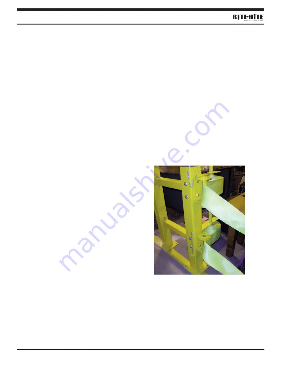
STRAP ATTACHMENT

Double Strap Restraining Kit with
Storage System

Unroll the strap and drop the loop end over the
latch bar. The smooth side of the strap should
face the side expecting the most impacts. Do
not fasten the strap to the latch bar at this time.

Remove any twists in the strap and insert the
non-looped end of the strap through the slots in
the tensioner at the opposite end of the
opening. 

Continue pulling and insert the end of
the strap behind the pressure strap on the
storage rod. These bolts will be tightened later
after the strap lengths are matched. Repeat
this process for the second strap.

Double Strap Restraining Kit with

Storage System

Figure 9

Summary of Contents for GUARDRITE STRAP

Page 1: ...TED IN U S A PUBLICATION NO GUARDRITE STRAP REV 3 1 RITE HITE PRINT SHOP OCTOBER 2013 THIS MANUAL COVERS ALL UNITS SHIPPED APRIL 2006 TO DATE GUARDRITE STRAP BARRIER SYSTEM INSTALLATION AND OWNER S MA...

Page 2: ...600 ORIGINAL INSTRUCTIONS ENGLISH The English version of this manual shall prevail over any error in or conflicting interpretation of any translations The RITE HITE products in this manual may be cove...

Page 3: ...clearly note that repairs are under way and state who is responsible for the lockout condition Tagout devices have to be constructed and printed so that exposure to weather conditions or wet and damp...

Page 4: ...O GUARDRITE STRAP REV 3 1 JUNE 2013 TOOLS AND COMPONENTS TOOLS REQUIRED 1 Hammer Drill 1 3 4 Concrete Bit for Hammer Drill Minimum 6 long 1 Impact wrench with 15 16 socket 2 3 4 Rachet 2 3 4 Combinati...

Page 5: ...BARRIER DOUBLE POSTS PEDESTRIAN BARRIER ONLY SINGLE POSTS 10 000 LBS MOVING AT 4 MPH Figure 2 NOTICE To be properly positioned the straps must be fully horizontal with all slack removed The lock pin m...

Page 6: ...brackets or the storage system brackets TENSIONER BRACKET INSTALLATION Use the x 6 5 bolts and lock nuts provided to fasten the U shaped tensioner bracket to the post Note that you may be using the s...

Page 7: ...ttach the pressure straps to the storage rod Do not tighten hardware at this time One pressure strap should get attached for each strap that will be rolled up LATCH BRACKET INSTALLATION Position the l...

Page 8: ...installed completely See the previous photo of the latch plate and the post cap STRAP ATTACHMENT Double Strap Restraining Kit with Storage System Unroll the strap and drop the loop end over the latch...

Page 9: ...e crank mechanism on the storage rod to roll up the straps around the rod Continue to roll up the straps until the straps are completely stored If the straps do not store evenly it may be necessary to...

Page 10: ...peat this process for the second strap Store the tensioner bar Go to the other side of the system and remove the latch bar from the latch bracket and lay it on the ground Return to the storage system...

Page 11: ...ove the lock pin to continue tensioning the strap Tension the strap until it is completely horizontal and it does not have any slack or sag Fully insert the lock pin through the tensioner and tensione...

Page 12: ...GUARDRITE STRAP REV 3 1 JUNE 2013 PARTS 7 3 3 675 1 33 7 21 7 3 25 758 33 7 21 8 5 5 7 675 3 7 0 3 57 180 5 6 5 37 21 7 3267 7 3 8 5 5 7 675 3 7 3267 51 017 5 57 6753 7 6725 8 5 5 7 675 3 6 7 7 56751...

Page 13: ...PUB NO GUARDRITE STRAP REV 3 1 JUNE 2013 13 GUARDRITE STRAP SYSTEM BARRIER 6 1 3267 7 7 0 47 3 57 180 5 6 5 37 21 3267 6 1 8 5 5 7 675 3 3 3267 5 7 7 55 5 8 5 5 7 675 3 3 8 3 67 1 25 21 5 7 1...

Page 14: ...3 5 675 1 1 7 7 0 47 3 57 180 5 6 5 37 21 6 7 675 3 55 5 5 57 675 3 5 7 1 25 675 3 8 5 5 7 675 3 71615 6322 8 5 5 7 675 3 6 5 5 73 1 5 7 50 3 1 2 71615 8 5 5 7 675 3 187 1 2 1 6 5 7 1 6 5 06 5 1 5 7...

Page 15: ...REV 3 1 JUNE 2013 15 GUARDRITE STRAP SYSTEM BARRIER 675 3 6725 6 67 0 7 0 47 3 57 180 5 6 5 37 21 5 1 6 8 5 5 7 675 3 6 5 06 6 7 1 3 7 35 6685 8 5 5 7 675 3 187 1 2 1 5 7 5 1 017 8 5 5 7 675 3 187 1...

Page 16: ...ER 16 PUB NO GUARDRITE STRAP REV 3 1 JUNE 2013 5 1 25 0 17 3267 7 7 0 47 3 57 180 5 6 5 37 21 3267 6 1 8 5 5 7 675 3 3 3267 8 5 5 7 3267 2 1 5 8 5 5 7 675 3 55 5 8 5 5 7 675 3 187 1 2 1 6 5 7 1 6 5 06...

Page 17: ...E STRAP SYSTEM BARRIER 6 1 675 3 5 675 1 1 7 7 0 47 3 57 180 5 6 5 37 21 3 1 2 71615 8 5 5 7 675 3 71615 6322 8 5 5 7 675 3 5 7 1 25 675 3 8 5 5 7 675 3 6 7 7 7 56751 7 5 57 6753 5 7 16 21 5 8 5 5 7 6...

Page 18: ...GUARDRITE STRAP SYSTEM BARRIER 18 PUB NO GUARDRITE STRAP REV 3 1 JUNE 2013 NOTES...

Page 19: ...PUB NO GUARDRITE STRAP REV 3 1 JUNE 2013 19 GUARDRITE STRAP SYSTEM BARRIER...

Page 20: ...nty is RITE HITE exclusive warranty RITE HITE EXPRESSLY DISCLAIMS ALL IMPLIED WARRANTIES INCLUDING THE IMPLIED WARRANTIES OF MERCHANTABILITY AND FITNESS Non standard RITE HITE warranties if any must b...

Reviews:

Related manuals for GUARDRITE STRAP