18
Pub. 1147 - Rev. 7 SEPTEMBER 2004
Mechanical Dock Leveler Hydraulic Conversion
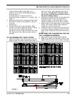
T-Strut base (Dim "L"). See Figure 9.
7. On the Safe-T-Strut, measure the distance from the
top of the collar to the distance you measured on the
leveler. Subtract 2 inches from this measurement
and draw a line at this position on the strut.
See Figure 9.
8. Cut the Safe-T-Strut at the line.
9. Slide the drill template that is provided onto the cut
end of the Safe-T-Strut. Clamp the template in place
when the edge is flush with the end of the strut.
10. Drill a 1/4" dia. pilot hole through the strut. Remove
the template and enlarge the hole using a 5/8"
diameter drill.
11. Using the hoist, raise the leveler and install the Safe-
T-Strut.
12. Drill holes in concrete pit floor. Fasten the pit floor
bracket securely using (6) 5/8" diameter bolts that
are a minimum of 4" long.
13. Insert clevis pin through pit floor bracket. Lock pins
in place with cotter pins.
ANCHORING REAR OF LEVELER
Securely anchor the rear frame of the
leveler in a minimum of (2) locations to the pit floor
or rear pit wall. This is done to eliminate any frame
movement when the deck is being raised. Use 5/8”
diameter anchors that are a minimum of 4” long.
TOE GUARD INSTALLATION
1. Install toe guards to leveler. Insure no binding will
occur during leveler operation. Be sure to also check
for interference on a below dock loading situation.
PUMP/HOSES INSTALLATION (STANDARD)
1. Install pump assembly under leveler in a position
that is easy to access for maintenance, yet clear
from impact when the leveler is bottomed out below
dock. Weld support bracket to frame.
2. Install 90
o
elbows in pump and cylinders.
3. Turn adapter onto 90
o
elbow of ramp cylinder. Fasten
securely.
4. Install velocity fuse into adapter of ramp cylinder.
Fasten securely.
5. Install hoses between the pump and the ramp and
lip cylinders. The small hose should be connected to
the lip cylinder and the larger hose should get
fastened the velocity fuse on the ramp cylinder.
6
Install breather on ramp cylinder.
7. Fill oil reservoir to level indicated on tank. Use MIL-
H-5606 oil.
PUMP/HOSES INSTALLATION (REMOTE
PIT)
1. Install pump assembly in the remote location. Insure
that the hose length provided will be sufficient to
reach both hydraulic cylinders during the full range
of leveler motion.
2. Install 90
o
elbows in pump and cylinders.
3. Turn adapter onto 90
o
elbow of ramp cylinder. Fasten
securely.
4. Install velocity fuse into adapter of ramp cylinder.
Fasten securely.
5. Install hoses between the pump and the ramp and
lip cylinders. The small hose should be connected to
the lip cylinder and the larger hose should get
fastened the velocity fuse on the ramp cylinder.
6. Install breathers in cylinders.
7. Fill oil reservoir to level indicated on tank. Use MIL-
H-5606 oil.
INSTALLATION OF OPTIONAL ARTD
SYSTEM
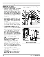
1. Slide ARTD subassembly over the lip cylinder and
pin the subassembly in place using the rear cylinder
pin on the lip cylinder.
2. Using hose clamp provided, fasten front of ARTD
assembly securely to the front of the lip cylinder at
the 1” spacer on the bracket.
3. Locate bolt and washer that will secure slide rod and
apply lok-tight to the threads. Securely tighten bolt
through slide rod into front lip cylinder hinge pin. See
Figures 17A & B and parts list in back of manual.
4. Route wiring from switch back to motor junction box.
Fasten securely to stringers.
5. Weld restrictor limit switch bracket to center stringer
3” forward from center of ramp cylinder pin. If
necessary, it is acceptable to mount the switch plate
to the ramp bracket. See figure 16.
6. Install restrictor limit switch.
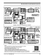
7. Wire per schematics on Figures 18-27.
FIGURE 13


