background image

Safe-T-Gate™ Swing 

Installation/Owner’s Manual

 Rite-Hite

®

Publication No. 

54450050  October 2015

INSTALLATION

NOTICE

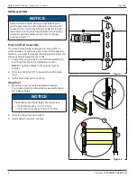
Install the Safe-T-Gate Swing so pedestrians must 


pull the gate open to enter a dangerous area. A safe 

access point is created by forcing people to stop and 

look before entering. Pushing the Safe-T-Gate Swing 

should provide immediate egress from the danger 

zone (see Figure 1). 

Post and Rail Assembly 

The Safe-T-Gate Swing is designed to swing 90°s in 

either direction. To allow the gate to open in the opposite 

direction, you need to relocate the stopping block from it's 

factory assembled position (A) to (B). 

1. 

Temporarily position the 

Post and Rail

 assembly (D) 

and 

Stop Post 

(E) at the installation location.

NOTE:

The 

Base Plates

 of (F) and (E) must be 

parallel. 

2. 

Shim the 

Pivot Post

 (F) to be plumb and the 

Rails


level. 

3. 

Install 

Pivot Post 

with 4 anchors.

Stop Post

1. 

Move the 

Stop Post

 to it's installation location. 


The ordered unit size should be measured between 

the 2 

Base Plates

.

NOTICE

The 

Rail Bracket

 should (approximately) clear:

• 

the post bumper by 1/16” [1.6 mm]

• 

the 5” [127mm] post by 17/32” [13.5 mm]

2. 

Shim the 

Stop Post 

as required. 

3. 

Install 

Stop Post 

with 4 anchors.

 B

 A

 E

 F

 D

Figure 1 

Figure 2 

Summary of Contents for SAFE-T-GATE Swing

Page 1: ...ublication No 54450050 October 2015 SAFE T GATE SWING This Installation Owner s manual covers units shipped June 2015 to Date Safety 2 Specifications 3 Installation 4 5 Maintenance 6 Parts 7 Warranty...

Page 2: ...anchors and 1 Owner s Manual SAFETY Safety Identifications DANGER Indicates a hazardous situation which if not avoided will result in death or serious injury Indique une situation dangereuse qui si el...

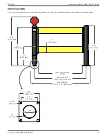
Page 3: ...size is defined by the Clear Opening Width C O W as measured between the inside of the base plates 53 14 1349 4 mm 43 75 1111 3 mm 7 177 8 mm 21 533 4 mm 42 1066 8 mm Clear Opening Width C O W Post Ce...

Page 4: ...to open in the opposite direction you need to relocate the stopping block from it s factory assembled position A to B 1 Temporarily position the Post and Rail assembly D and Stop Post E at the instal...

Page 5: ...removing or attaching the Bracket 1 Remove the 3 1 4 20 bolts and lock washers A that secure the internal mechanism to the Post 2 Slide the Bracket with Rails up until it separates from the Pivot Post...

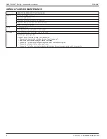
Page 6: ...Cracks and holes Mounting hardware on bottom of rails is tight Operation Open Close the gate Adjust the force as required Squeaking or grinding noises If the gate doesn t operate smoothly or makes noi...

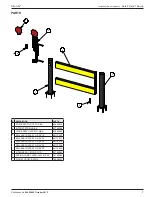
Page 7: ...50036 2 KIT POST STG RND BK 53760084 3 HINGE ASSY GATE STG S BK 52500065 4 RAIL ASSY GATE STG S 36 YE 66110030 RAIL ASSY GATE STG S 42 YE 66110031 RAIL ASSY GATE STG S 48 YE 66110032 RAIL ASSY GATE ST...

Page 8: ...n failure to operate the Product within the Product s rated capacities and or specified design parameters or failure to properly maintain the Product iv use of the Product in a manner that is inconsis...

Reviews: