3 Device description
EN
14
Rittal Liquid Cooling Package
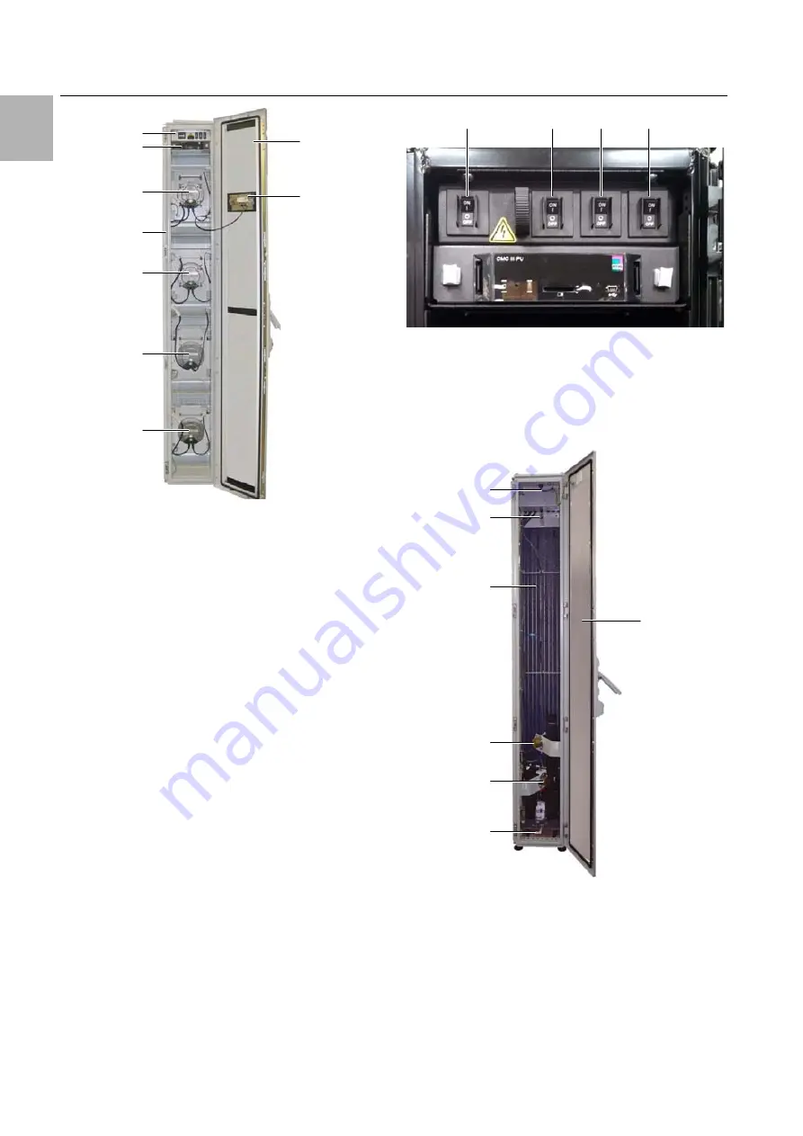
Fig. 12:
LCP Inline flush front – open front door
Key
1
LCP door
2
Installation location for optional display with touch
function
3
Fans (in this instance, fully equipped with 4 fans)
4
Rack
5
Control unit CMC III PU (see fig. 10, item 13)
6
Fuse box with master switch (see fig. 10, item 1)
The fuse box is comprised of the following compo-
nents:
– Thermally activated master switch
– 3 thermally activated switches for fan pairs 1/2, 3/4
and 5/6
– AC/DC power pack for CMC III PU supply
– EMC line filter
Fig. 13:
Fuse box with master switch
Key
1
Thermally activated switch, fan pair 1/2
2
Thermally activated switch, fan pair 3/4
3
Thermally activated switch, fan pair 5/6
4
Thermally activated master switch
Fig. 14:
LCP Rack rear – rear door open
Key
1
LCP rear door
2
Condensate collecting tray and condensate dis-
charge
3
Water connection, return
4
Water connection, inlet
5
Air/water heat exchanger
6
Vent valve
7
Mains connection, network connection and connec-
tion of optional condensate pump
1
2
6
5
3
3
4
3
3
1
2
3
4
1
7
5
2
6
3
4


