3 Device description
EN
16
Rittal Liquid Cooling Package
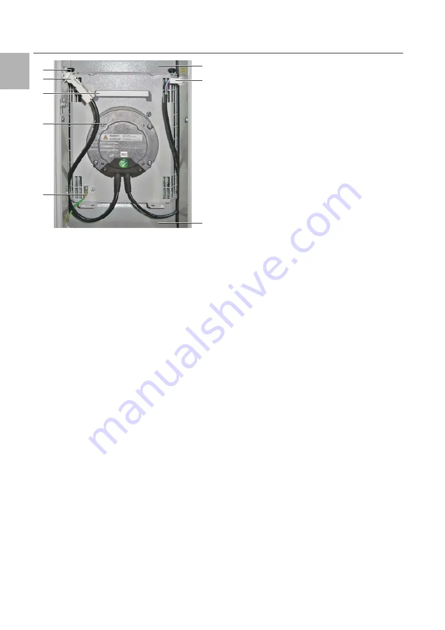
Fig. 16:
Fan module in fan tray – LCP Inline flush version
Key
1
Air baffle plate
2
Connector DC
3
Earth connection
4
Fan
5
Handle
6
Connector AC
7
Screws
A fan module is essentially comprised of the fan itself.
All fan modules are controlled by a shared control unit
(RLCP fan) which is mounted in the upper section of
the Liquid Cooling Package. The fans may be operat-
ed with linear control from 0%–100%.
The fan modules are installed on rack-mounted
shelves in the front section of the Liquid Cooling
Package.
The two connection cables for the power supply and
pilot wire are routed out of the underside of the fan. In
the LCP Rack and LCP Inline, the intake end of the fan
module lies against a sealing section mounted on the
left and right of the rack, which forms an effective seal.
In the LCP Inline flush, the fans lie directly against the
rack. This means that in the installed state, the fans
are connected directly to the unit's air/water heat ex-
changer, enabling the air from the air/water heat ex-
changer to be routed directly and without interruption
to the fan module.
It takes about 2 minutes to replace a fan module dur-
ing operation (see section 5.3 "Fan installation").
3.3.5
Water module with cold water connection
A significant component of the water module is the
stainless steel condensate collecting tray, on which a
leak sensor and a condensate discharge are located.
In addition to the leak sensor, the condensate tray is
also equipped with a pressureless condensate dis-
charge. This directs the condensate out of the Liquid
Cooling Package to the rear. The hose must be con-
nected to an external discharge (see section 6.1.3
"Connecting the condensate discharge").
The pipework for the Liquid Cooling Package's cool-
ing water connection (inlet and return) runs above the
condensate collecting tray.
The lines connect the rear-mounted cooling water
connection with the air/water heat exchanger built into
the front of the device. The lines are insulated to avoid
the formation of condensation. A motorised control
valve is located in the cooling water inlet line to control
the cooling water flow.
The control unit of the water module is fitted in the up-
per section, below the power supply to the Liquid
Cooling Package.
The cooling water connection is connected to the
main inlet and return connections by two 1½" external-
ly threaded pipes for flange gaskets. The connection
nozzles are positioned horizontally to the rear.
The cooling water connection to the cold water net-
work can be made by either rigid pipework or flexible
hoses, which are available from the Rittal accessory
range (see section 15 "Accessories").
3.4
Proper and improper usage
The Liquid Cooling Package is used to dissipate high
heat losses and effectively cool devices built into a
server enclosure. The unit is designed solely for sta-
tionary use in sealed rooms.
The unit is state of the art and built according to rec-
ognised safety regulations. Nevertheless, improper
use can present a hazard to life and limb of the user
or third parties, or result in possible damage to the
system and other property.
Consequently, the unit must only be used properly
and in a technically sound condition.
Any malfunctions which impair safety should be recti-
fied immediately. Follow the operating instructions!
Proper use also includes following the operating in-
structions and fulfilling the inspection and mainte-
nance conditions.
Inappropriate use may result in danger. Inappropriate
use may include:
– Use of impermissible tools.
– Improper use.
– Improper rectification of malfunctions.
5
6
4
2
1
3
7
1


