3 Device description
EN
12
Rittal Liquid Cooling Package
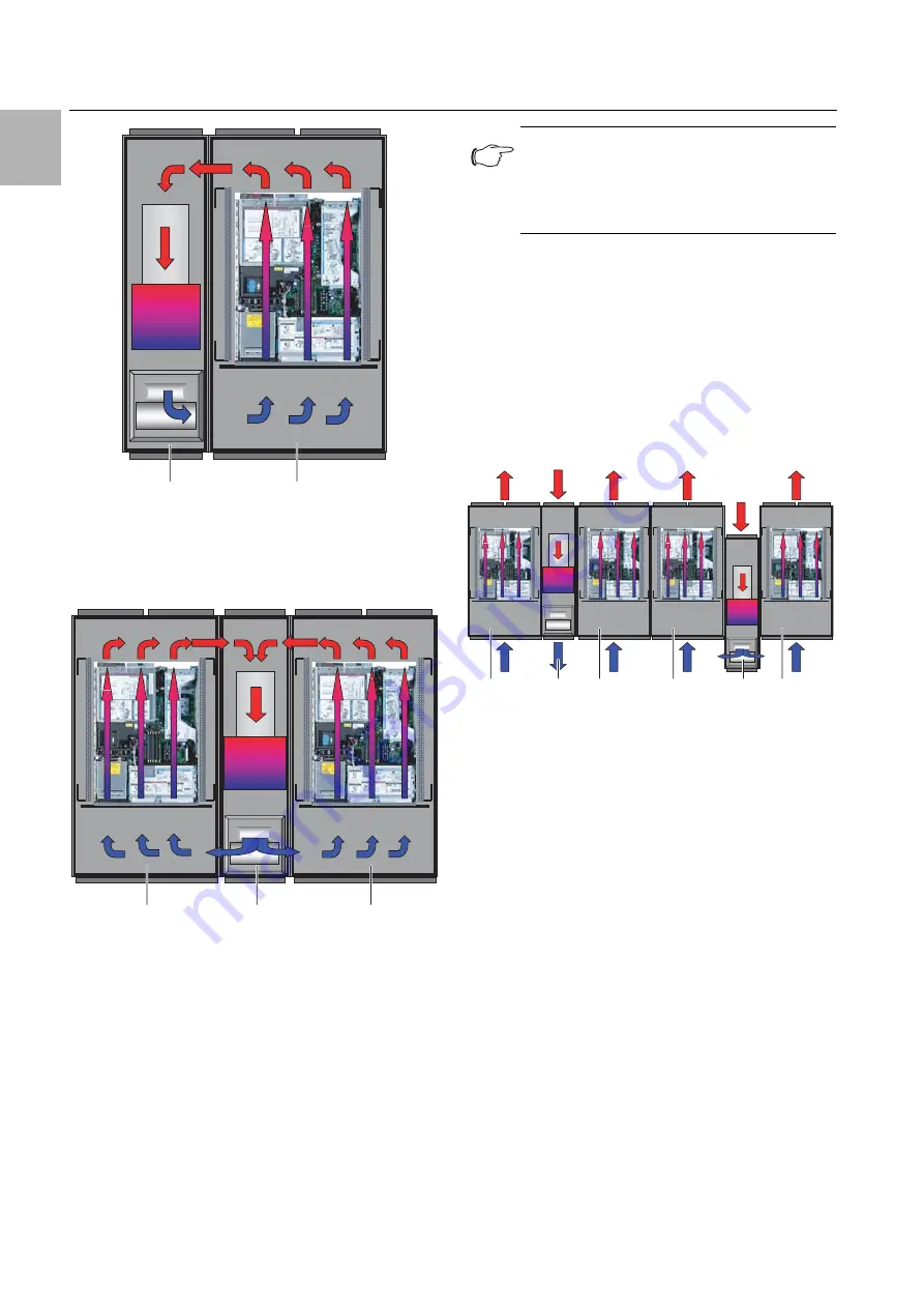
Fig. 7:
Air routing with a bayed server enclosure – top view
Key
1
LCP Rack
2
Server enclosure
Fig. 8:
Air routing with two bayed server enclosures – top
view
Key
1
Server enclosure
2
LCP Rack
The system consisting of the LCP Rack and the server
enclosure should be sealed as effectively as possible
in order to prevent the loss of cooling air. To accom-
plish this, the enclosure is equipped with side panels,
roof and gland plates. Any existing cable entries
should be sealed e.g. using suitable brush strips.
Whilst the system is in operation, both the front and the
rear doors should be kept completely shut.
3.2.3
LCP Inline and LCP Inline flush
Targeted air routing by hot air extraction from the hot
aisle and cold air blown into the cold aisle has a fun-
damental effect on the amount of heat to be dissipat-
ed.
In order to achieve sufficient cooling in the server en-
closure, it is important to ensure that the cooling air
passes through the interior of the built-in units and is
unable to flow past at the sides.
Fig. 9:
Air routing with bayed server enclosures – top view
Key
1
LCP Inline
2
Server enclosure
3
LCP Inline flush
For this purpose, the system consisting of LCP Inline
or LCP Inline flush, server enclosure and cold aisle
containment should be sealed as effectively as possi-
ble in order to avoid a decrease in cooling capacity
due to mixing of cold and hot air. This is achieved by
sealing the cold aisle with doors at the beginning and
end of the rack rows, and sealed against the ceiling
with roof elements. Existing cable entry glands are ad-
ditionally sealed e.g. with suitable brush strips.
2
1
2
1
1
Note:
However, the system does not need to be
completely airtight, thanks to the high, coor-
dinated air throughputs of the server and
LCP fans.
2
1
3
2
2
2


