background image

9

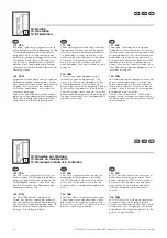
PDR/PDM Montageanleitung/PDR/PDM assembly instructions/PDR/PDM – Notice de montage


D

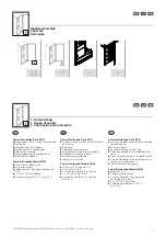
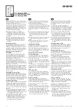
Ausführung PDR

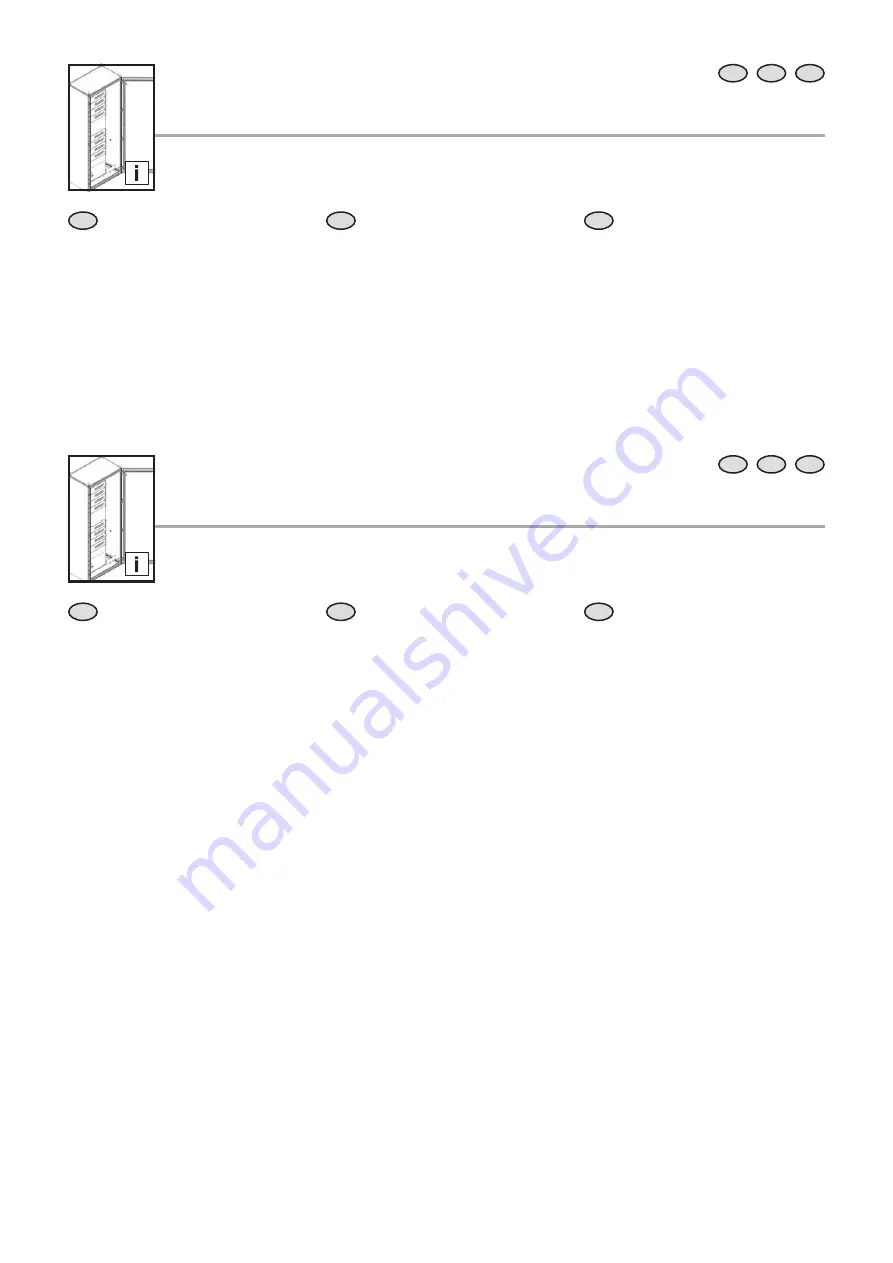
Das PDR modular basiert auf einem TS 8 
Schrankgerüst mit einer frontseitig asym-
metrisch verbauten 19˝-Montageebene. In 
diese werden die zusätzlich benötigten PDM 
Abgangsmodule eingeschoben und ver-
schraubt. Rückseitig ist ein vollständig gekap-
seltes Stromschienensystem verbaut, welches 
die PDM Module einspeist. Im unteren Bereich 
befi ndet sich die Einspeisung, rechts der 
Raum für die Kabelführung im Schrank.

Optional kann das PDR auch mit einer ande-
ren Türvariante geliefert werden.

EN

Confi guration of PDR

The basic structure of the PDR is provided 
by a TS 8 rack. In the front area there is a 19" 
mounting level installed permitting fastening 
and guiding of the PDMs. In the rear cov-
ered area the power distribution by means 
of busbars and connectors for the individual 
modules is located. In the lower section of the 
PDR the infeed and the main switch are found.

Optionally, the Rittal PDR is also available with 
base/plinth, glazed door, sheet steel door 
ventilated and/or non-ventilated etc.

F

Confi guration PDR

Le PDR modulaire s'appuie sur une ossature 
d'armoire TS 8 avec un plan de montage 
19" monté asymétriquement en façade. Les 
modules de sortie PDM nécessaires y sont 
intégrés et vissés. Un système de rail de 
distribution totalement intégré alimentant les 
modules PDM est monté à l'arrière. Dans la 
partie inférieure se trouve l'alimentation, à 
droite de la zone pour le guidage des câbles 
dans l'armoire.

En option, le PDR peut également être fourni 
avec un autre modèle de porte.

 5. Power Distribution Rack (PDR)
5. Power Distribution Rack (PDR)

EN

F

D


D

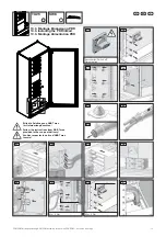
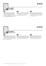
Ausführung PDM

Das Rittal PDM kann sowohl im PDR direkt in 
das vorgegebene Raster eingeschoben oder 
auch in bestehende Racks mit 19˝ eingebaut 
werden.

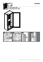
PDM im PDR

Die Module können in eine freie Position im 
vorgegebenen Raster in das PDR einge-
schoben werden. Durch die 4 Schrauben im 
19˝-Profi l ist das PDM zu sichern. Verriegelt 
werden die Module über einen an den Haupt-
schalter gekoppelten Vorreiber. Das Lösen ist 
nur möglich, wenn vorher durch Abschalten 
des Hauptschalters entriegelt wird. Nun kann 
das Modul durch Lösen der Schrauben im 
19˝-Profi l entfernt werden.
Die Versorgung mit Spannung geschieht im 
Fall des PDR über Steckverbinder, welche 
durch des Einschieben des PDM in das PDR 
kontaktieren.

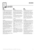
PDM im 19˝-Rack

Ist das PDM in einem beliebigen 19˝-System 
bzw. Schrank eingebaut, muss das Modul 
in geeigneter Weise mit Spannung aus der 
Hauptverteilung oder einer CEE-Steckdose 
versorgt werden. Dies ist über die separat 
erhältliche PDM-Anschlussleitung zu realisie-
ren.

Die PDM-Anschlussleitung hat die Best.-Nr. 
7857.351.

Bitte Vorsicherung beachten! 
Siehe Hinweise auf dem Typenschild.

Die Kabelabfangung und -sicherung erfolgt 
mittels beiliegendem Kabelbügel am einge-
setzten Gehäuse bzw. Schrank.

EN

Confi guring the PDM

The Rittal PDM can be inserted directly into 
the preconfi gured compartment of the PDR, or 
installed in existing 19" racks.

PDM in the PDR

The modules can be inserted into one of the 
unoccupied compartments of the PDR. The 
PDM is secured via the 4 screws on the 19" 
rack. The modules are locked in place by 
means of a fastener connected to the master 
switch. They can only be removed by fi rst 
unlocking them by switching off  the master 
switch. At this point, the module can be 
removed by taking out the screws in the 19" 
rack.
When confi gured with the PDR, voltage is sup-
plied via plugged connections, which contact 
when the PDM is inserted into the PDR.

PDM in the 19" rack

If the PDM is installed in any 19" system or 
enclosure, the module must be appropriately 
powered from the main distribution system or 
via a CEE plug. This is done using PDM con-
nection cables, available separately.

The Model No. for the PDM connection cable 
is 7857.351.

Make sure that a backup fuse is in place! 
See information on the rating plate.

Cables can be clamped and protected in the 
housing or enclosure by means of the included 
cable brackets.

F

Confi guration PDM

Le PDM Rittal peut être inséré directement 
dans la trame prévue dans le PDR ou être 
monté dans des baies 19˝ existantes. 

PDM dans le PDR

Les modules peuvent être intégrés à un 
emplacement libre dans la trame prévue 
dans le PDR. Les 4 vis dans le montant 19˝ 
permettent de sécuriser le PDM. Les modules 
sont maintenus par un verrouillage couplé 
sur le commutateur principal. Ils peuvent être 
retirés uniquement lorsque le déverrouillage a 
été réalisé auparavant par la désactivation du 
commutateur principal. À ce stade, le module 
s'enlève en retirant les vis du montant 19˝.
En utilisation avec un PDR, l'alimentation 
s'eff ectue par des connecteurs activés par 
l'insertion du PDM dans le PDR.

PDM dans la baie 19˝

Si le PDM est monté dans un système 19˝ ou 
une armoire quelconque, le module doit être 
alimenté en tension d'une manière adaptée, 
à partir de la distribution principale ou d'une 
prise CEE. Cette opération s'eff ectue par 
le câble de raccordement PDM disponible 
séparément.

Le câble de raccordement PDM porte la réfé-
rence 7857.351.

Veuillez tenir compte du fusible auxiliaire !
Cf. consignes sur la plaque signalétique.

Les câbles sont fi xés et protégés dans le 
boîtier ou l'armoire par les supports de câbles 
inclus.

 6. Power Distribution Modul (PDM)
6. Power Distribution Module (PDM)

EN

F

D

Summary of Contents for 7857.300

Page 1: ...Montage und Bedienungsanleitung Assembly and operating instructions Notice de montage et d emploi PDR PDM PDR PDM PDR PDM 7857 300 7857 310 7857 320 ...

Page 2: ...n 10 8 Technical specifications 8 1 PDR 11 8 2 PDM 11 9 Functions 9 1 PDR 12 9 2 PDM 12 10 Installation 10 1 Installing the PDR 13 10 2 Installing the PDM 14 10 3 Installing the PDR infeed 15 10 4 Installing the PDM in the PDR 16 11 Commissioning 11 1 PDR 17 11 2 PDM 17 12 Operation 12 1 PDR 18 12 2 PDM 18 13 Notes on maintenance 18 14 Cleaning 19 15 Disposal 19 16 Warranty 20 17 Customer service a...

Page 3: ...r door frame 䡲 Rear panel 䡲 Side panels and roof plate 䡲 Levelling feet incl base plinth adaptor 䡲 Earthing of all enclosure panels 䡲 Busbars touch protected 䡲 Integral master switch Power Distribution Module PDM 䡲 482 6 mm 19 module 3 U 䡲 Incl master switch 䡲 4 fused 3 phase outlets to the rack 䡲 3 x 230 V 16 A per outlet 䡲 Connection cables 400 V 3 phase max 63 A F Power Distribution Rack PDR 䡲 ...

Page 4: ...hnique suffisante pour le montage l instal lation sur site et le raccordement d armoires électriques selon les normes électriques électroniques mécaniques et pneumatiques en vigueur La notice d utilisation s adresse aux opérateurs et aux spécialistes formés pour la maintenance électrotechnique 2 1 Certification CE La déclaration de conformité peut être téléchargée depuis le site Internet de Rittal ...

Page 5: ...e expansion is easy by means of Power Distribution Modules PDM Power Distribution Rack PDR and Power Distribution Module PDM provide a revolutionary energy management for IT racks The modular power supply system allows for energy supply from the 250 A infeed through up to 8 plug in Power Distribution Modules PDM The PDR is destined exclusively for operation in the data centre The significant featur...

Page 6: ... completed in a few easy steps When system require ments increase the Power Distribution Module PDM can simply be expanded The Power Distribution Rack PDR and Power Distribu tion Module PDM represent a revolutionary approach to IT rack energy management The modular power supply system enables energy to be supplied from the 250 A infeed via up to 8 Power Distribution Modules PDM that can be plugged...

Page 7: ...ner Lådorna måste säkras under transport montering och installation så att de inte kan välta Uso conforme campi di applicazione I lavori sull impianto elettrico devono essere ese guiti esclusivamente da una persona avvertita PAV o persona esperta PES in conformità alla norma EN 50110 Questo prodotto può essere utilizzato esclusivamente come accessorio per la fornitura e la distribuzione di energia...

Page 8: ...i és műszaki termek Ettől eltérő alkalmazás esetén a Rittal lal kell konzultálni A termékek kizárólag a Rittal által előírt rendszertartozékkal kombinálhatók és üzemeltethetők Biztonsági tudnivalók A szekrényeket szállítás fel és kiépítés során feldőlés ellen biztosítani kell Naudojimas pagal paskirtį naudojimo sritys Darbus su elektros įrenginiais turi atlikti tik kvalifikuotas elektrikas pagal EN...

Page 9: ... werden Dies ist über die separat erhältliche PDM Anschlussleitung zu realisie ren Die PDM Anschlussleitung hat die Best Nr 7857 351 Bitte Vorsicherung beachten Siehe Hinweise auf dem Typenschild Die Kabelabfangung und sicherung erfolgt mittels beiliegendem Kabelbügel am einge setzten Gehäuse bzw Schrank EN Configuring the PDM The Rittal PDM can be inserted directly into the preconfigured compartmen...

Page 10: ...d in electro technics These persons are instructed by a skilled electrician in respect of the necessary protec tive equipment and safeguarding measures In addition they are instructed on the possible hazards of inappropriate behaviour and are trained for the particular work if necessary It is necessary for the person instructed in electro technics to take notice of and to understand the installati...

Page 11: ...EMC environment Environnement CEM 1 EN 61439 1 8 1 PDR PDR PDR Schrankart Type of enclosure Type d armoire TS 8 Schrankhöhe Enclosure height Hauteur de l armoire 1200 2000 mm Breite Width Largeur ca approx 800 mm Tiefe Depth Profondeur ca approx 500 mm Gewicht Weight Poids ca approx 180 kg ohne Verpackung ohne Module without packaging without modules sans emballage sans modules Potenzialausgleich ...

Page 12: ...TN C network 230 V 400 V 3 phase 250 A In this case a cross connector is applied at the infeed between N and PE model Wei dmüller WQV 70 2 model no 106350 9 2 PDM Functionality of the Rittal PDM mainly lies in power distribution within a data centre from the main distribution system at the PSM busbars to the racks or distribution of power from the PDR PSMs can be provided with 3 phase 400 230 V 16...

Page 13: ... in the gland plate The floor must be flat and level for installa tion It must be sufficiently firm to ensure safe fastening of the enclosure to the floor e g with fastening plugs The enclosure must be connected firmly with the floor under all circumstances in order to prevent tilting Baying with TS 8 enclosures on the sides or at the rear is possible For information on baying installation and necessary...

Page 14: ...g angle Installation in enclosure with 19 mounting angles The PDM is secured in its 19 compartment using the accessory screws Use of slide rails part no DK 7063 000 is recommended to brace the PDM housing If the infeed is connected via CEEkon plugs connection cable DK 7857 351 must be used The fuse indicated on the rating plate must be provided The infeed may only be plugged or unplugged when the ...

Page 15: ... 3 1 10 3 Montage Einspeisung PDR 10 3 Installing the PDR infeed 10 3 Montage Alimentation PDR Ausschalten Switch off Désactivation 1 3 MD 4 Nm TX25 4 Bitte die Anleitung von ABB Tmax im Lieferumfang beachten Follow the instructions from ABB Tmax provided in the scope of delivery Veuillez respecter la notice d ABB Tmax fournie 4 6x M5 x 10 8x M6x16 SW8 ...

Page 16: ...M Montageanleitung PDR PDM assembly instructions PDR PDM Notice de montage 1 2 EN F D 1 2 2 1 2 2 1 1 10 4 Montage PDM in PDR 10 4 Installing the PDM in the PDR 10 4 Montage PDM dans le PDR MD 4 Nm TX25 4x M6x16 ...

Page 17: ...ed rack must be inspected for any electri cal equipment installed there that is engaged or any possible contact with parts under hazardous voltage Turning on the power without prior inspection may result in electric shock when working with connected electrical devices The infeed line must also be inspected for safe installation All master switches and automated circuit breakers of the plugged in P...

Page 18: ...ncteur de protection doit pouvoir être identifiée à tout moment Prenez garde aux personnes se trouvant dans la zone de l instal lation électrique lorsque des équipements sont raccordés et alimentés 12 2 PDM Les fusibles déclenchés peuvent être réactivés en cours de fonctionnement Il convient de vérifier au préalable la raison pour laquelle le fusible s est déclenché La cause du déclen chement le cou...

Page 19: ...cun liquide ou agent nettoyant agressif ne doit être utilisé L humidité ne doit en aucun cas péné trer dans l armoire afin d éviter toute corrosion ou tout choc électrique EN F D 15 Entsorgung 15 Disposal 15 Mise au rebut D Da die Rittal PDR und PDM hauptsächlich aus den Bestandteilen Stahl Kupfer und Kunststoff bestehen sind die Geräte für den Fall dass sie nicht mehr benötigt werden der Entsorgun...

Page 20: ...ine et en Inde constituent les bases pour garantir un service après vente mondial rapide et efficace en s appuyant sur le réseau de toutes les filiales et agents Rittal à travers le monde Headquarter Deutschland Headquarters Germany Siège en Allemagne RITTAL GmbH Co KG Auf dem Stützelberg D 35745 Herborn Phone 49 0 2772 505 1855 Fax 49 0 2772 505 1850 E mail service rittal de Service HUB USA Servic...

Page 21: ...21 PDR PDM Montageanleitung PDR PDM assembly instructions PDR PDM Notice de montage Notizen Notes ...

Page 22: ...res Power Distribution Climate Control IT Infrastructure Software Services www rittal com contact You can find the contact details of all Rittal companies throughout the world here 09 2016 D 0000 00000647 Rev00 ...

Reviews: