Installation and Operation
UPS-Manual
11
EN
3.5.1. True RS232 Port Descriptions
The RS232 interface shall be set as follows:
Baud Rate
2400 bps
Data Length
8 bits
Stop Bit
1 bit
Parity
None
The Pin Assignments of the true RS232 port
are illustrated as follows:
•
To be continually supplied via Bypass
without shut down
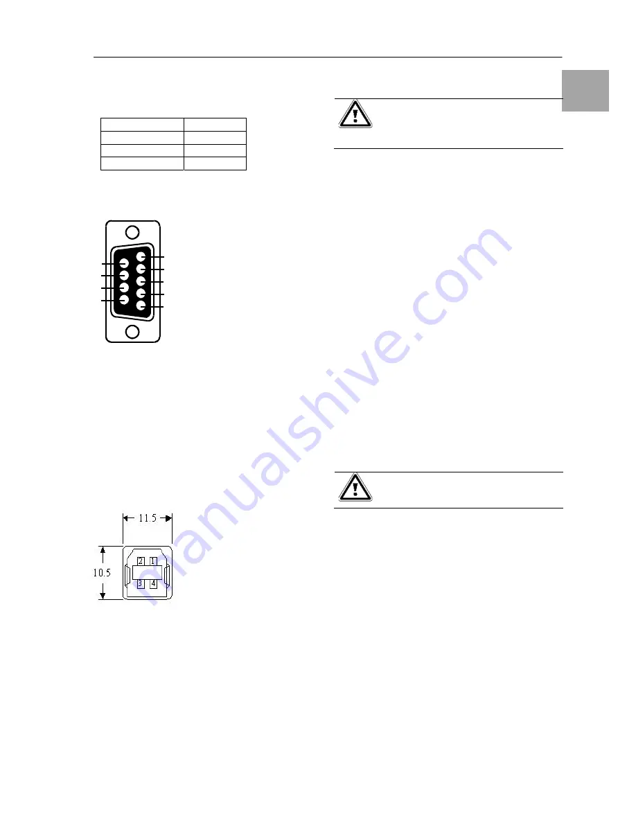
3.5.2. USB Port Descriptions
The USB communication protocol definition as
below:
1. Comply with USB version 1.0, 1.5Mbps
2. Comply with USB HID Version 1.0.
3. The Pin Assignments of the USB port:
3.5.3.
EPO (Emergency Power Off)
The Pin assignments of the EPO Input port are:
1
Æ
EPO+
2
Æ
Ground
To enable the EPO function, please short Pin 1
& 2.
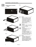
4. Installation and Operation
Warning!
Read the Safety Instruction guide
(page 5 to 6) before installing the
UPS!
4.1. Unpacking
Inspect the UPS upon receipt. The manufac-
turer designed robust packaging for your prod-
uct. However, accidents and damage may oc-
cur during shipment. Notify the forwarder and
dealer if there is damage.
The packaging is recyclable; save it for reuse
or dispose of it properly.
•
Remove the UPS from the carton box.
•
Check the package contents. Standard
content shall includes:
-
1 set of User's Manual
-
2 pcs of IEC output cables (for UPS with
IEC sockets only)
-
1 pc of AC Input Power Cord
-
1 set of UPS communication software with
RS232 and USB cable
-
1 set of Tower/Rack Accessories Kit
4.2. Selecting Installation Position
Warning!
The UPS is heavy.
Select a location sturdy enough to handle the
UPS weight. To ensure proper operation and
long operating life, always position the UPS
according to the following requirement:
1.
Keep minimum 20cm (8 inches) distance
clearance from the rear panel of the UPS to
avoid any obstructions.
2.
Do not block the air-flow to the ventilation
louvers of the unit.
3.
Please ensure the installation site is free
from excessive dust and the ambient tem-
perature and humidity should be within the
specified limits.
4. Do not place the UPS in a dusty or corrosive
environment or near any flammable objects.
1
2
3
4
5
6
7
8
9
Pin 3: RS232 Rx
Pin 2: RS232 Tx
Pin 5: Ground
1
Æ
VCC (+5V)
2
Æ
D
-
3
Æ
D +
4
Æ
Ground


