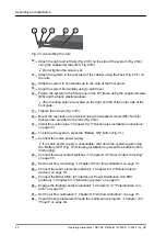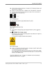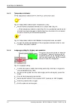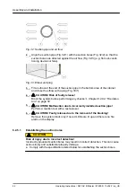
If the second fire alarm threshold is reached (the relay output
“Fire alarm”
is trig-
gered), the release device is triggered electrically upon conclusion of an analysis
period, whereby the propellant cartridge (Fig. 5/2) is opened and the foaming agent
flows into the tank (Fig. 5/1). The relay output
“Extinguishing”
is triggered. The
foaming agent forces the extinguishing agent through the discharge nozzle
(Fig. 5/12) into the switch cabinet to be protected so that the required concentration
is generated.
The fill level monitoring, which is integrated in the tank, reports an extinguishing
agent loss to the electronic evaluation unit, which then shows this failure
(extinguishing agent loss) on the display. The relay output
“Common failure”
is trig-
gered.
The power supply for the system is ensured by means of 2 sources. On the one
hand, by a power supply unit (Fig. 5/10), which also takes control of charging the
batteries for the emergency power supply (Fig. 5/11). On the other hand, by the
emergency power supply itself, which is switched into parallel standby conditions.
The emergency power supply is configured for a 4-hour uninterrupted operation of
the system.
The operation and display of the current state of the system is by means of the
control panel that is installed. To display the current state, this has, on the one hand,
6 LED indicators and, on the other hand, an LCD display. The LEDs serve to display
the main alarms and failures (
Chapter 8.1 “LED displays” on page 67
), while the
individual states are shown in detail in the display as plain text.
If there are several messages pending, the cursor buttons can be used to switch
between each individual message. The messages present are sorted according to
priority and according to the order in which they were lodged. If the cursor buttons
are not actuated within 30 seconds, the display switches back to the basic state.
The display of statuses by means of the LEDs (
) on the control panel is independent from the content of the display
and, consequently, from scrolling with the cursor buttons and always shows the cur-
rent state of the system.
In addition to the cursor buttons, the control panel has 2 additional
[Reset]
buttons
for resetting stored messages.
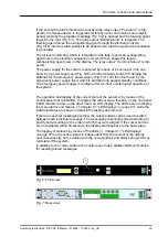
Fig. 6: Front view
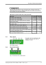
Fig. 7: Rear view
Structure, function and connections
Operating Instructions / DET-AC III Master / 916005 / 11-2022 / en_US
29

