5
Structure, function and connections
5.1
Structure
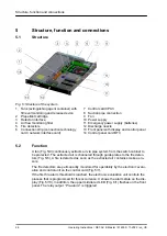
Fig. 5: Structure of the system
1 Tank (extinguishing agent container) with
fill level monitoring and release device
2 Propellant cartridge
3 Detector interface
4 Air flow monitoring filter
5 Fire detectors
6 Connection strip (connection technology
card / network interface card)
7 Control card CPU3
8 Suction pipe connection
9 Fan
10 Power supply
11 Emergency power supply (batteries)
12 Discharge nozzle
13 Front panel with display and control panel
14 Control panel card BT3
5.2
Function
A fan (Fig. 5/9) continuously extracts air via pipe system from the switch cabinet to
be protected. The extracted air is channeled through guide plates to the fire detec-
tors (Fig. 5/5). A fire is detected as soon as the extracted air contains smoke aero-
sols.
The fire detectors are permanently monitored for operability by the electronic evalu-
ation and control unit on the control card (Fig. 5/7).
If the first fire alarm threshold is reached, the electronic evaluation unit controls the
process that is programmed for this occurrence: It shows the alarm state on the dis-
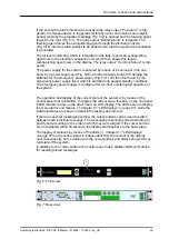
play (Fig. 5/13). In addition, the upper middle red LED (Fig. 6/1) flashes on the front
panel. The relay output
“Pre-alarm”
is triggered.
Structure, function and connections
Operating Instructions / DET-AC III Master / 916005 / 11-2022 / en_US
28

