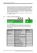
5.3
Connections
1
2
3
4
5
6
7
8
9
10
11
12
13
14
15
16
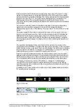
Fig. 8: "AT3 connection technology" card (left) and "NW network interface" card
(right)
1 Connecting terminal for relay output
„
Pre-alarm
2 Connecting terminal for relay output
„
Fire alarm
”
3 Connecting terminal for relay output
„
Extinguishing
”
4 Connecting terminal for relay output
„
Common failure
”
5 Plug (RJ12) for door contact switch connection
6 Plug (RJ12) for connection to Rittal Monitoring System (
„
failure
”
5.3.3 “Interfaces to the Monitoring System” on page 32
7 Plug (RJ12) for connection to Rittal Monitoring System (
„
fire alarm
”
5.3.3 “Interfaces to the Monitoring System” on page 32
8 Plug (RJ12) for connection to Rittal Monitoring System (
„
pre
‑
alarm
”
5.3.3 “Interfaces to the Monitoring System” on page 32
9 Connection for networking "DET-AC III Master - DET-AC III Slave" (RJ12-DEC)
Chapter 5.3.9 “Connection for networking” on page 34
Chapter 5.3.4 “Connection of external alarm device”
(delivery with terminating resistor 47
Ω
and diode 1N4007)
11 Connection for external fill level monitoring and triggering of external tank
Chapter 5.3.5 “Connection of external fill level monitoring and triggering of
(only activated in the aspirating smoke detection
system EFD III)
12 Plug for manual call point (delivery with terminating resistor 1,8 k
Ω
)
5.3.6 “Manual call point connection” on page 33
13 Door contact plug 2 (delivery with two terminating resistors: 1,8 k
Ω
and 470
Ω
)
Chapter 5.3.2 “Door contact switch” on page 31
14 Power supply (U
B
Chapter 5.3.7 “Power supply” on page 34
15 USB port (type B)
Chapter 5.3.8 “USB port” on page 34
16 CAN bus interface (RJ45)
Chapter 5.3.3 “Interfaces to the Monitoring System”
Wiring
The following applies to wires: Each of the wires to be used must not be longer than
30 m (98 ft) per clamp connection. The minimum wire cross section is 0.5 mm
2
(AWG 21).
Structure, function and connections
Operating Instructions / DET-AC III Master / 916005 / 11-2022 / en_US
30

