INFORMATION
The information provided above does not apply for the connection cable to the
Monitoring System. Details on cabling and the cable cross-section can be found in
the instructions of the Monitoring System.
Mechanical connection data of the clamp connection
Wire type
minimum maximum
Conductor cross section rigid
0.34 mm
2
2.5 mm
2
Conductor cross section flexible
0.2 mm
2
2.5 mm
2
Conductor cross section flexible with wire end ferrule,
without plastic sleeve
0.25 mm
2
2.5 mm
2
Conductor cross section flexible with wire end ferrule,
with plastic sleeve
0.25 mm
2
2.5 mm
2
Conductor cross section flexible AWG/kcmil
24
12
Two conductors of equal cross sections rigid
0.2 mm
2
1 mm
2
Two conductors of equal cross sections flexible
0.2 mm
2
1.5 mm
2
Two conductors of equal cross sections flexible with wire
end ferrule without plastic sleeve
0.25 mm
2
1 mm
2
Two conductors of equal cross sections flexible with twin
wire end ferrule with plastic sleeve
0.5 mm
2
1.5 mm
2
5.3.1
Relay outputs
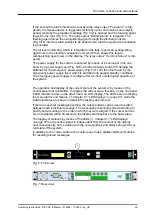
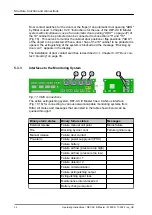
The system has four potential-free relay
outputs (Fig. 9/1 to 4) each with one
changeover contact.
5.3.2
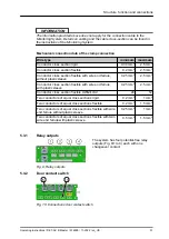
Door contact switch
5
13
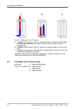
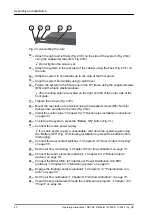
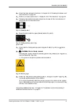
Fig. 10: Connections door contact switch
Fig. 9: Relay outputs
Structure, function and connections
Operating Instructions / DET-AC III Master / 916005 / 11-2022 / en_US
31


