6.2.7
Setting air flow calibration
How to set the air flow calibration is described in
Chapter 8.6 “Air flow calibration”
10% is to be set as the permissible deviation from the total measured air flow, as
contamination of the suction holes is recognized as early as possible at this setting.
If frequent air flow failure messages appear due to flow conditions, the analysis time
prior to failure evaluation should be increased first of all. As a further measure, the
deviation from the actual set flow value can be raised by 20% or 40%.
The door to the protected cabinet must be
closed immediately following the start of air
flow calibration. The door must not be
opened again until the counter has incre-
mented and the air flow is displayed. Now
set the deviation from the actual set flow
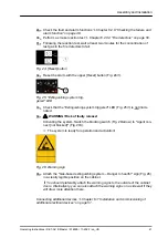
value and confirm with the button
[Reset PS]
INFORMATION
The air flow must be recalibrated when changing the equipment of the switch cab-
inet.
6.2.8
Checking the failure and alarm function
The system is ready for operation when the door is closed: The green LED lights up
and
“State OK”
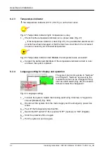
is shown in the display. If this is not the case, actuate the upper
[Reset]
button (Fig. 39/1). The green LED then blinks twice and messages that are
still pending are reset.
INFORMATION
Switch the system into the revision state for inspection
on page 80. Transmissions are blocked by this.
6.2.8.1
Air flow
By using residue-free removable insulating tape to cover up the suction holes, the
extracted air flow is reduced and a blockage is simulated. The message
“Failure
(too low) air flow”
should now appear in the display. Remove the insulating tape
from the suction pipe after checking the air flow. The message
“Failure (too low) air
flow”
is reset automatically.
Fig. 38: [Reset PS] button
Fig. 39: [Reset] button
Assembly and installation
Operating Instructions / DET-AC III Master / 916005 / 11-2022 / en_US
48


