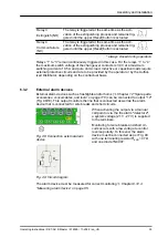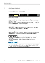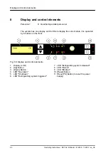
Relay 3
Extinguish (NO)
The relay is triggered at the same time as the acti-
vation of the extinguishing process and remains trig-
gered until the upper
[Reset]
button is actuated.
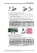
Relay 4
Common failure
(NC)
The relay is triggered at the same time as the acti-
vation of the extinguishing process and remains trig-
gered until the upper
[Reset]
button is actuated.
*
)
always closed during operation
Relays “1” to “3” remain continuously triggered in this case. For the relays “1” to “4”
the maximum switch voltage of the changeover contacts is 30 V at a maximum
switching current of 0.5 A and pure ohmic load. Inductive or capacitive loads require
external protective circuits and are to be provided by the operator or by the Author-
ized Distributor, depending on the contractual basis.
6.3.2
External alarm devices
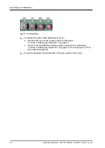
External alarm devices such as flashlights and/or horns (
accessories, consumables, and tools” on page 116
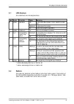
) can be connected to output "10"
(Fig. 48/10). This output monitors the line that is connected as well as the alarm
device that is connected for wire breaks and short circuits.
When activating the output via a manual
call point or via the fire alarm "detector 2",
a system voltage (21 V - 27 V) is supplied
to the terminals.
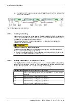
Monitoring for wire breaks and short cir-
cuits occurs with a low voltage to control
reverse polarity. To this end, the alarm
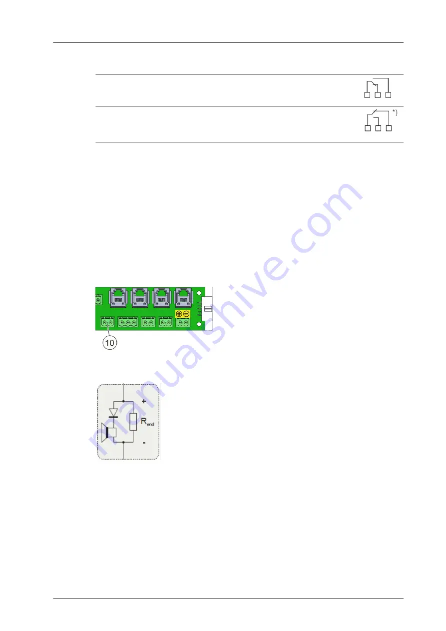
device must be connected as per Fig. 49
with one terminating resistor R
END
= 47 Ω
and one diode 1N4007.
The alarm device must be measured for correct monitoring
“Measuring alarm device” on page 85
Fig. 48: Connection external alarm
device
Fig. 49: Circuit diagram
Assembly and installation
Operating Instructions / DET-AC III Master / 916005 / 11-2022 / en_US
53


