3
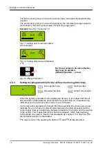
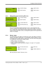
Upper limit value of the monitoring currently set
4
Representation of the current measured value as a bar
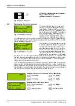
The current measured value is determined and the associated thresholds are calcu-
lated from it according to the selected width of the monitoring window (
±
10 %,
±
20 % or
±
40 %). 10 % is to be set as the permissible deviation using the arrow but-
tons
“Monitoring window smaller”
/
“Monitoring window bigger”
, as contamination of
the suction holes is recognized as early as possible at this setting.
The standard EN 54-20 is no longer complied with at a setting greater than 20 %.
The deviations can be seen in the upper left and upper right side of the display.
If frequent air flow failure messages appear due to flow conditions, the time prior to
the failure being displayed should be increased first of all. The tolerance can be
raised by 20 or 40 % as a further measure.
For the determined values become
effective, they must be adopted
([Reset PS] button Fig. 72/1).
8.6.2
Manual calibration of the air flow monitoring
INFORMATION
Prior to manual calibration, an automatic calibration including setting the thresholds
(
±
10 %,
±
20 % or
±
40 %) must be performed and confirmed
matic calibration of the air flow monitoring” on page 74.
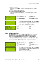
Determining the current values
The current values are determined. The value displayed
counts up to 64 (progress bar). No further operation is possible
at this stage.
Wait for this stage to be concluded.
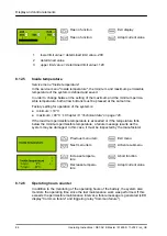
Monitoring range
upwards
Abort function
Monitoring range
downwards
Adopt current value
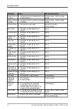
1
Lower limit value of the monitoring currently set
2
Current measured value
3
Upper limit value of the monitoring currently set
4
Representation of the current measured value as a bar
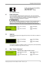
Fig. 72: [Reset PS] button
Display and control elements
Operating Instructions / DET-AC III Master / 916005 / 11-2022 / en_US
75


