10
Rittal CMC III coded lock VX
6 Operation
EN
6
Operation
6.1 Activating the coded lock
After connecting the coded lock to an Access Control/
DCM using the connection cable, the coded lock starts
automatically (see section 5.4 "Connecting the coded
lock"). Separate activation is not required.
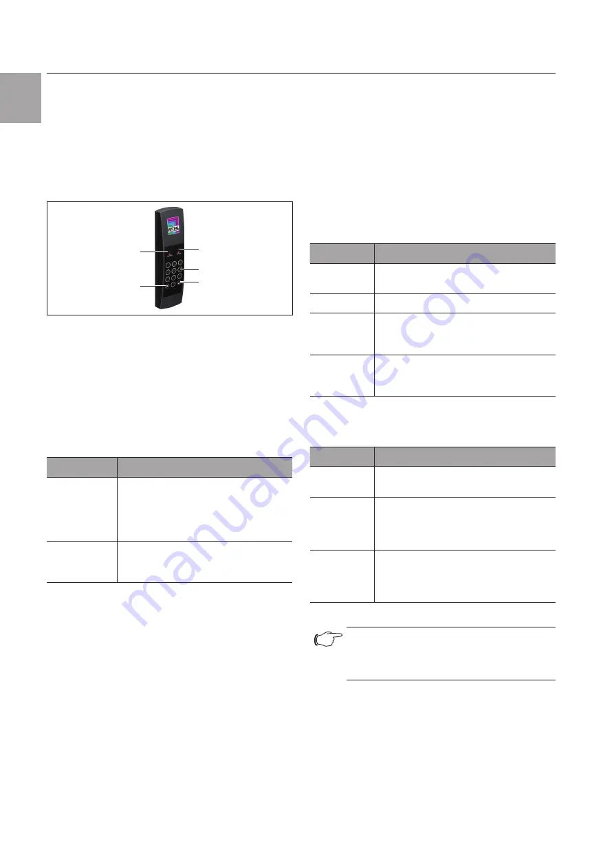
6.2 Operating and display elements
4
5
1
3
2
Fig. 5:
Front of the coded lock
Legend
1
"ERROR" LED (white)
2
Number keys 0-9
3
"Enter" key
4
"Clear" key
5
"ACCESS" LED (white)
6.3 LED displays
Two LEDs for the status display are integrated into the
front of the coded lock (Fig. 5, item 1 and item 5).
Designation
Status
ACCESS
If the connection is correct, continuously
flashes every 5-10 seconds.
If an authorised access code combina-
tion is entered, the LED lights up contin-
uously for approx. 2 seconds.
ERROR
If an unauthorised number combination
is entered, both LEDs (ACCESS and ER-
ROR) flash together every 5-10 seconds.
Tab. 1:
LED flashing codes
6.4 Operating the CMC III Processing Unit
from the website
After logging on to the CMC III Processing Unit, the
web interface for operating the device is displayed.
6.4.1 Configuration tab
Access authorisation settings can be made in the "Se-
curity" group frame in the
Configuration
tab.
◾ First select the "Processing Unit" node in the naviga-
tion area.
◾ Select the
Configuration
tab in the configuration
area.
Regardless of the next work steps:
◾ In the
Security
group frame, click on the
Access
Configuration
button.
The "Access Configurations" dialogue opens.
To add a new access code:
◾ Below the list of access codes/transponder cards
that have already been added in the "Access Config-
urations" dialogue, click on the
Add
button.
To configure an access code:
◾ Select the line with the required entry to change the
configurations stored for this.
◾ Click the
Edit
button.
The "Access Configuration" dialogue opens.
Parameter
Explanation
Type
Configuration of an access. The "Key-
code" entry must be selected here.
Code
Enter the required access code.
User
Selection of the user authorised for the
access. The user must have been created
in advance.
Information
Specific additional information for the ac-
cess. This text is also added for the user
in the CMC III Processing Unit logfile.
Tab. 2:
"Access Configuration" dialogue
All connected access modules are displayed in tabular
form.
Parameter
Explanation
Use
Enable or disable individual access mod-
ules.
Device
Name
Specific description of the Access Con-
trol/DCM or (virtual) access controller to
which the access module to be switched
is connected.
Serial Num-
ber
Serial number of the Access Control/DCM
or (virtual) access controller to which the
access module to be switched is con-
nected.
Tab. 3:
"Devices" table
Note:
A user must be assigned to the access
code. Otherwise, access isn't possible even
with the appropriate access code.
To delete an access authorisation via access
code:
◾ Select the line with the required entry you wish to
delete.
◾ If necessary, select another entry by keeping the shift
key pressed. All lines from the first entry selected to
the last entry selected (inclusive) are selected.


