Rittal CMC III coded lock VX
9
5 Installation
EN
55
44
KB 40x40
M
A
= 2,5 Nm
Ø4,5
Ø8
166
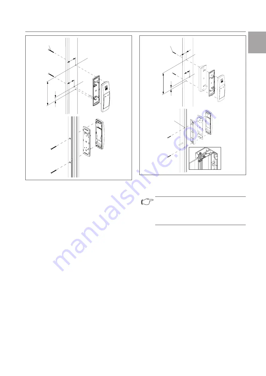
Fig. 3:
VX glazed door installation
5.3.4 Installation on a VX IT glazed door or VX IT
vented door
The installation on the frame of a VX IT glazed door
or VX IT vented door is performed with the provided
compensating panel.
◾ First dismantle the locking bars.
◾ Drill suitably sized holes at the required part of the
frame of the VX IT glazed door (Fig. 4).
◾ Use a 90° countersink to deburr the holes for cable
entry.
◾ Clean away any splinters at the point where the cod-
ed lock is to be attached.
◾ Attach the compensating panel incl. coded lock to
the prepared location using the flat-headed screws
provided.
◾ Finally, reattach the locking bars.
13
37,5
KB 40x30
M
A
= 2,5 Nm
Ø4,5
Ø8
166
23
Ø9,4x90°
Ø4,5
Option
Fig. 4:
VX IT glazed door, VX IT vented door installation
5.4 Connecting the coded lock
Note:
The coded lock is compatible with the
CMC III Access Control (DK 7030.202)
and the Door Control Module (DCM,
DK 7030.501).
The Access Control/DCM supplies the coded lock with
the necessary operating voltage via the connection
cable. A separate power supply unit does not need to
be connected.
◾ First disconnect the CAN bus from the Access Con-
trol/DCM.
◾ Fit the associated handle to the door to be moni-
tored.
◾ Connect this handle via the connection cable to the
Access Control/DCM.
◾ Connect the coded lock via the connection cable to
the Access Control/DCM.
◾ Connect the CAN bus to the Access Control/DCM
again.


