13
11. Configuration and internal components
– non-intrinsically safe circuits
Use Ex terminal blocks that comply with EN 60079-7 Section
13.
These Ex components are part of an Ex apparatus, and as such
they may only be used together with a partially certified enclo-
sure. All approved terminal blocks are partially certified and are
marked with a "U" next to the approval number.
Mount the terminal blocks on mounting rails. Depending on the
type of terminal you are using, attach an end plate to the open
side of the terminal block and an end bracket to the beginning
and end of the terminal block to attach the block.
Drawing number A0204207KE00 contains information on how
to install the different variations of mounting rails.
The tensioning torques and the associated terminal cross-
sections should be obtained from the terminal manufacturer’s
operating instructions.
12. Clearance and creepage distances,
spacing
Creepage distances and clearances as well as spacing
(refer to drawing A0204207KE00).
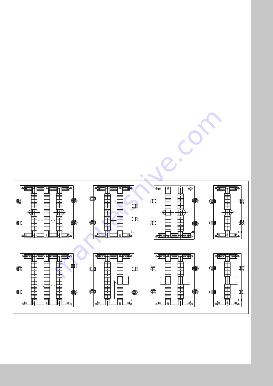
See the attachment for spacing between intrinsically safe and
non-intrinsically safe circuits and terminals.
11. Bestückung, Einbauten – nichteigen-
sicherer Stromkreise
Zur Klemmenbestückung sind Ex-Reihenklemmen nach EN
60079-7 Abschnitt 13 zu verwenden.
Diese Ex-Bauteile sind Teil eines Ex-Betriebsmittels und dürfen
als solche nur in Verbindung mit einem teilbescheinigten Ge-
häuse verwendet werden. Alle zulässigen Reihenklemmen sind
teilbescheinigt und tragen zur Kennzeichnung neben der Zulas-
sungsnummer ein U.
Die Reihenklemmen werden auf Tragschienen befestigt; je nach
Klemmentyp wird am Ende die offene Klemmenseite mit einer
Abschlussplatte versehen und an Anfang und Ende der Klem-
menreihe je ein Endwinkel zur Fixierung gesetzt.
Die Einbaumöglichkeiten der Varianten der Tragschienenbefesti-
gung ergibt sich aus Zeichn.-Nr. A0204207KE00.
Die Anzugsdrehmomente und die zugehörigen Klemmenquer-
schnitte sind der Betriebsanleitung der Klemmenhersteller zu
entnehmen.
12. Luft- und Kriechstrecken, Einbauab-
stände
Luft- und Kriechstrecken sowie Einbauabstände
(s. Zeichn.-Nr. A0204207KE00).
Für Abstände zwischen eigensicheren und nicht eigensicheren
Stromkreisen und Klemmen siehe Abbildung.
50
50
50
50
Ex e
Ex e
Ex e
Ex e
Ex e
Ex i
Ex i
Ex i
50
50
50
50
50
50
50
Ex e
Ex e
Ex e
Ex e
Ex e
Ex e
Ex e
Ex e
Ex e
Ex i
Ex i
Ex i
Ex i
Ex i
Ex i
Ex i
Ex i
50
50
50
50


