background image

18

Operating and Maintenance Instructions – 4  Design and function

Rittal Liquid Cooling Package Plus

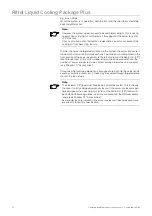
4.1.4 Water module with cold


water connection

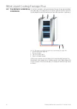
Fig. 9:

Water module with cold water connection

1

Two-way control valve

2

Leakage sensor

3

Cooling water flow with temperature sensor

4

Cooling water return with temperature sensor

5

Condensate pump

6

Condensate sensor (floating switch)

7

Flow sensor

8

Condensate collecting tray

A significant component of the water module is the stainless steel condensate 
collecting tray, on which a level sensor, a condensate pump, and a condensate 
overflow are located.

A hose line leads the condensate from the condensate pump out of the Liquid 
Cooling Package Plus through the rear. Additionally, the condensate tray is 
equipped with a no pressure condensate overflow in case either the level sen-
sor or the condensate pump should malfunction. This is located underneath the 
condensate pump and also leads the condensate to the rear, out of the Liquid 
Cooling Package Plus. Both hoses should be connected to either a collecting 
device or an external drain.

The pipework for the Liquid Cooling Package's Plus cooling water connection 
(inlet and return) runs on the side, above the condensate collecting tray. The 
lines connect the rear-mounted cooling water connection with the air/water heat 
exchanger that is built into the front of the device. The lines are insulated to avo-
id the formation of condensation. A motor-operated control valve is located in 
the cooling water return line. This control valve can control the cooling water 
flow.

The control unit of the water module is mounted with a holder on a separate 
mounting plate directly behind the rear door of the Liquid Cooling Package 
Plus, above the water module at the level of the lower fan module.

The cooling water connection is connected to the main connections of the coo-
ling water return by two 1" externally threaded pipes. The connecting pieces of 
both pipes are composed of T pieces, to allow for the option of connecting from 
the rear or through the raised floor. 

The cooling water connection to the cold water network can be made by either 
rigid pipework or flexible hoses, which are available from the Rittal accessory 
range (Model No. SK 3301.351).

8

6 5

4

1

2

3

7

Summary of Contents for Liquid Cooling Package Plus SK 3301.480 230 V

Page 1: ...Rittal Liquid Cooling Package Plus Operating and Maintenance Instructions Rittal Liquid Cooling Package Plus Model No SK 3301 480 230 400 V version ...

Page 2: ...text and to Chapter 2 Safety instructions This is the prerequisite for secure assembly of the Liquid Cooling Package Plus safe handling and the most trouble free operation possible Please keep the complete documentation readily available so that it is always on hand when needed We wish you every success Your Rittal GmbH Co KG Rittal GmbH Co KG Auf dem Stützelberg 35745 Herborn Germany Tel 49 0 27 ...

Page 3: ... 4 1 1 Liquid Cooling Package Plus 14 4 1 2 Air water heat exchanger 16 4 1 3 Fan module 16 4 1 4 Water module with cold water connection 18 4 2 Function 19 4 3 Air routing inside the enclosure 22 4 3 1 Possibilities for establishing redundancies 24 5 Technical specifications 26 6 Installation Getting Started 27 6 1 Installation conditions 27 6 2 Assembling the Liquid Cooling Package Plus 28 6 2 1...

Page 4: ... 76 7 3 1 Staus LED 77 8 Maintenance 78 9 Troubleshooting 79 10 Frequently asked questions FAQ 81 11 Glossary 85 12 Spare parts 87 13 Accessories 88 13 1 Accessories Liquid Cooling Package 88 13 2 Accessories from the rack program 88 14 Further technical information 89 14 1 Hydrological information 89 14 2 Characteristic curves 90 14 2 1 Cooling output 90 14 2 2 Pressure loss 91 14 3 Overview diag...

Page 5: ...accordance with the following directives EU EMC directive 89 336 EEC annex 92 31EC and 93 68 EC EU Low Voltage Directive 2006 95 EC EN 55022 Information technology equipment Radio disturbance characteristics EN 60335 1 Safety for household and similar electrical appliances Part 1 General requirements EN 61000 3 2 Electromagnetic compatibility EMC Part 3 2 Limits Limits for harmonic current emissio...

Page 6: ... will be liable for damages All rights created by a patent grant or re gistration of a utility model or design are reserved 1 2 7 Revision Rev 1 of 19 April 2007 Year of construction Fabr Nr Production No Luft Wasser Wärmetauscher Air water heat exchanger Echangeur de temperature air eau Lucht Water Warmtewisselaar Luft vatten vaermevaexlare Scambiatore di calore ad aria acqua Intercambiador de ca...

Page 7: ...Cooling Package Plus 1 3 Product description 1 3 1 Unit components Fig 2 Liquid Cooling Package Plus front 1 Rack H x W x D 2000 mm x 300 mm x 1200 mm 2 LCP door 3 Touch panel 4 Wall plate wide with air outlet 5 Wall plate narrow with air inlet 6 Levelling foot 5 4 6 3 2 1 ...

Page 8: ...eless improper use can present a hazard to life and limb of the user or third parties or result in possible impairment of the system and other property The unit should thus only be used properly and in technically sound condition Any malfunctions which impair safety should be rectified immediately Follow the operating instructions Intended use also includes following the operating instructions and...

Page 9: ...ning symbol is used to indicate great dangers caused by the product which may result in injury and even death if the indicated pre ventative measures are not followed Caution This warning symbol is used to indicate procedures which may cause risk of equipment damage or personal injury Note This instruction symbol indicates information concerning individual proce dures explanations or tips for simp...

Page 10: ...mbient conditions for which the unit is designed are com plied with e g temperature humidity air purity Caution Risk of malfunction or damage All media necessary for the control system e g cooling water must be available during the entire operating time Caution Risk of malfunction or damage In order to avoid frost damage the minimum permissible input water temperature of 6 C must not be undercut a...

Page 11: ...Liquid Cooling Package Plus fulfils the requirements of EU directive 2002 95 EC on the Restriction of Use of Certain Hazardous Substances in Electrical and Electronic Equipment RoHS of 13 February 2003 Note Corresponding information concerning the RoHS directive is provided by our firm on the Internet at www rittal de RoHS ...

Page 12: ...densate pump 1 Condensate hose emergency overflow 1 Sealing strip 1 Connection plug 1 Cable tie and spreading anchor 1 Jumper for connection plug strain relief for connection cable 4 Eyebolts 1 Assembly instructions Caution Because of its height and small base the Liquid Cooling Package Plus is subject to tipping Risk of toppling especially after the unit is remo ved from the pallet Caution Transp...

Page 13: ...age Plus 1 Control unit Basic CMC 2 Fan 1 3 Fan 2 4 Fan 3 5 Fan 4 6 Fan 5 7 Fan 6 8 Air water heat exchanger 9 Water module The Liquid Cooling Package Plus consists of a superordinate control unit Basic CMC a water module a heat exchanger and six fan modules Fans in groups of two and the water module contain their own electronic controls 3 x RLCP fan and 1 x RLCP water which are connected to one a...

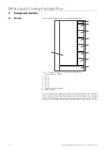
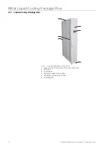
Page 14: ...l Liquid Cooling Package Plus 4 1 1 Liquid Cooling Package Plus Fig 5 Liquid Cooling Package Plus front 1 Rack H x W x D 2000 mm x 300 mm x 1200 mm 2 LCP door 3 Touch panel 4 Wall plate wide with air outlet 5 Wall plate narrow with air inlet 6 Levelling foot 5 4 6 3 2 1 ...

Page 15: ...form the cold air section together with the divider plate and the built in air water heat ex changer The wall plates have been punched with air outlet openings along their entire length in the front and rear to ensure cold air supply to the server and rejected hot air supply to the heat exchanger The narrower wall plates close off the rear of the device and form the warm air section together with ...

Page 16: ...xchanger is covered with a spray eliminator on the air outlet side that catches any occurring condensate and directs it to the condensate collecting tray in the Liquid Coo ling Package Plus Three temperature sensors are mounted on the front side of the spray eliminator at the level of the fan modules The sensors record the tem perature of the cold air that is blown in server in temperature and tra...

Page 17: ...ir outlet vent of the fan projects forward from a circular opening on the vertical plate piece When the fan mo dule is installed the air outlet vent extends into the cold air section of the device and facilitates a trouble free and direct routing of the air from the fan module to the air water heat exchanger Because the individual fan modules are located on separate angle brackets it is possible t...

Page 18: ...nnected to either a collecting device or an external drain The pipework for the Liquid Cooling Package s Plus cooling water connection inlet and return runs on the side above the condensate collecting tray The lines connect the rear mounted cooling water connection with the air water heat exchanger that is built into the front of the device The lines are insulated to avo id the formation of conden...

Page 19: ...n two server enclosures Together with the bayed server enclosures the Liquid Cooling Package Plus forms an airtight cooling system with horizontal air routing It places no additio nal demands on the room s climate control system The air routing in the LCP Plus supports the front to back cooling principle of the devices built into the server enclosure The fan modules draw the warm air exhausted fro...

Page 20: ...riable can open from 0 to 100 In addition the tempera ture differential between the cold air that is blown in and the warm air that is drawn is used to determine and set the fan speed The control attempts to keep the air temperature constant in front of the 482 6 mm 19 level by activating the control valve Any condensate which may develop is collected in the condensate collecting tray that is inte...

Page 21: ...ructions 4 Design and function Rittal Liquid Cooling Package Plus Fig 13 Mollier h x diagram for humid air Water Temperature Rel humidity E n t h a l p y Mollier h x diagram for humid air pressure 0 950 bar 537 000 m 10 000 C 80 000 rF ...

Page 22: ... the built in units and may not flow to the side Fig 14 Air routing of a bayed server enclosure top view 1 Liquid Cooling Package Plus 2 Server enclosure Fig 15 Air routing of two bayed server enclosures top view 1 Server enclosure 2 Liquid Cooling Package Plus In addition the system consisting of the Liquid Cooling Package Plus and the server enclosure should be sealed as well as possible in orde...

Page 23: ...throughput are built into the server enclo sure e g switches router etc these may be cooled through targeted place ment of the foam strips Note However the system does not need to be completely airtight This is not ne cessary due to the high coordinated air throughput of the server fans and LCP Plus fans In fact a small amount of ambient air is desirable since this can prevent the cooling air from...

Page 24: ...oo ling Package Plus makes it possible to achieve differing levels of redundancy Fig 16 Redundant or double cooling with two Liquid Cooling Packages Plus 1 Liquid Cooling Package Plus 2 Server enclosure 3 Inlet cold water system 4 Return cold water system Two server enclosures may be cooled with 3 Liquid Cooling Packages Plus Depending on the cooling output the device bayed in the middle between t...

Page 25: ...1 Liquid Cooling Package Plus 2 Server enclosure 3 Inlet cold water system 4 Return cold water system Fig 18 Redundant cooling and doubled alternating water supply 1 Liquid Cooling Package Plus 2 Server enclosure 3 Inlet cold water system 1 4 Return cold water system 1 5 Inlet cold water system 2 6 Return cold water system 2 3 4 2 1 2 1 1 5 6 3 4 2 1 2 1 1 2 1 2 1 ...

Page 26: ... 8 60 Pre fuse T A 16 0 10 0 Duty cycle 100 Capacity W Hz 2400 50 2650 60 Useful cooling output L37W15 kW Hz at 15 C inlet temperature and a volumetric flow of 60 l min 28 50 28 60 Air throughput of fans m3 h Hz max 5000 Coolant Water glycol mixture up to 30 Coolant inlet temperature C 6 to 20 ideally 15 Permissible operating pressure pmax bar 5 Ambient temperature range C 6 to 35 Noise level dB A...

Page 27: ...romagnetic interference Interfering electrical installations high frequency should be avoided Type of connection Connection description Power connection 230 V 50 60 Hz with connection cable DK 7856 026 16 A 1 CEE connector 3 pole 400 V 3 N PE 50 60 Hz with connection cable DK 7856 025 16 A 3 CEE connector 5 pole Cooling water connection 6 C to 20 C inlet temperature 5 bar permissible operating pre...

Page 28: ... horizontally divided into warm air and cold air sections by sealing the 482 6 mm 19 level Proceed as follows to seal the 482 6 mm 19 level If the server enclosure is only partially configured seal the open sections of the 482 6 mm 19 level using blanking plates Screw these tightly into the server rack from the front side Fasten the broader Model No SK 3301 370 3301 320 of the two foam strips from...

Page 29: ...appropriate so that ultimately there is a cut out in the foam to the left or right in the height of each such device in the server rack Ensure that there are no gaps on the warm air side of the device Fig 20 item 3 Cut additional pieces from the foam strips with a sharp knife that are at least as long as the height of the built in devices Attach the foam strips to the cold air side of the devices ...

Page 30: ...hich may be present with corresponding brush strips or similar Dismantle the server enclosure door Before baying a Liquid Cooling Package Plus one or both of the server enclo sure doors must be dismantled so that the attachment points for the baying connectors are accessible and are not covered by a door edge 2 3 5 4 5 1 Note The Liquid Cooling Package Plus can as desired be bayed onto a server en...

Page 31: ...nge dismantling 1 Door hinges 2 Hinge bolt holding fixture 3 Hinge joint 4 Server enclosure door Remove the server enclosure door see Fig 21 Step B Note It is only necessary to dismantle a server enclosure door when the Liquid Cooling Package Plus is to be bayed onto a previously erected server en closure Otherwise this work is not necessary If the Liquid Cooling Package Plus is to be set up with ...

Page 32: ...er Dismantle the door of the Liquid Cooling Package Plus whose hinges are on the side on which the server enclosure is to be bayed Proceed as described in Chapter 6 2 1 Preparatory work on the server enclosure Loosen both assembly screws from the cover Fig 22 item 3 and remove the cover Fig 22 item 2 Using assembly screws fasten three baying connectors each Fig 23 item 3 onto the intended attachme...

Page 33: ...assembly screws fasten the baying connectors Fig 23 item 3 onto the intended attachment points in the frame on the front and rear sides of the server enclosure Fig 23 item 2 As needed press the Liquid Cooling Package Plus lightly against the server enclosure in order to bring the baying connectors into alignment with the attachment points Then check the stability of the Liquid Cooling Package Plus...

Page 34: ...anel mountings Fig 24 item 1 as symmetrically as pos sible onto the upper mounting rail of the LCP Plus and using your hand press them firmly in place Screw down the two side panel mounting brackets Fig 24 item 2 above and below in the middle of the mounting rail using one screw each Screw down 3 side panel holders Fig 24 item 3 onto each of the two side assembly rails with one screw each Fig 24 A...

Page 35: ...s defective it can be replaced during operation without tools quickly and easily 6 3 1 Removing a fan module Proceed as follows to remove a fan module Open the rear door of the Liquid Cooling Package Plus Fig 25 Fan plug in unit 1 Fan plug in unit 2 T handle 3 Handle Open the fan module lock by turning the T handle fig 25 item 2 anticlock wise a quarter of a rotation Fig 25 item 2 Fig 26 Opening t...

Page 36: ...ig 27 Pulling out the fan module Caution Risk of injury Only pull on the handle when removing the fan module There is a dan ger of trapping between the main carrier of the fan module and the edges of the gaps in the floor of the fan plug in unit Caution Risk of injury Risk of damage While pulling the fan module out of the fan plug in unit support it from below It cannot be held by the handle alone...

Page 37: ...y unscrew them Remove the control unit together with the holder Fig 28 item 1 and item 3 from the mounting plate Fig 28 item 2 and set it down outside the Liquid Cooling Package Plus Open the fan module lock by turning the T handle fig 25 item 2 anticlock wise a quarter of a rotation Fig 25 item 2 Using the handle Fig 25 item 3 pull the fan module completely out of the fan plug in unit 1 2 3 4 4 N...

Page 38: ... 3 2 Installing a fan module Proceed as follows to install a fan module Fig 29 Fan plug in unit 1 Fan plug in unit 2 T handle 3 Slide rails Place the fan module onto the slide rails Fig 29 item 3 of the fan plug in unit and push it in until it reaches the stop position Fig 30 Plugging in the fan module 1 3 2 3 ...

Page 39: ...er you have installed the lower fan module as described above you must then install the water module control unit Proceed as follows Fig 32 Water module control unit 1 Water module control unit RLCP water 2 Mounting plate 3 Control unit holder 4 Thumb screw Place the control unit together with the holder Fig 32 item 1 and item 3 onto the mounting plate Fig 32 item 2 in the Liquid Cooling Package P...

Page 40: ...p this electrical documentation readily available so that it is al ways on hand when needed This is the only documentation which is autho ritative for the unit Caution Work on electrical systems or equipment may only be carried out by an electrician or by trained personnel guided and supervised by an electri cian All work must be carried out in accordance with electrical engi neering regulations T...

Page 41: ...35 mm Leave the length of the PE conductor at approximately 45 mm Remove approximately 9 mm from the insulation of all conductors with a sui table tool Fig 33 Dimensions for removing the rubber cover and insulation Attach wire end ferrules without insulating collars to the ends of the conduc tors To crimp the wire end ferrules use a suitable crimping tool with an inte gral lock to prevent the tool...

Page 42: ... flexible cable to the strain relief housing with a cable clamp Fig 35 Connection plug with strain relief housing 1 Strain relief for conductors with Ø 12 mm 2 Strain relief for conductors with Ø 2 mm 1 2 Note The configuration of the Connection plug may be found in Chapter 14 4 Circuit diagram Danger Take upmost care not to short circuit one of the phases with the zero conductor or the earth cond...

Page 43: ...eutral conductor N and the phase conductor L to a length of ap proximately 35 mm Leave the length of the PE conductor at approximately 45 mm Remove approximately 9 mm from the insulation of all conductors with a sui table tool Fig 37 Dimensions for removing the rubber cover and insulation Attach wire end ferrules without insulating collars to the ends of the conduc tors To crimp the wire end ferru...

Page 44: ...e connection cable The connection cable must be fastened for the electrical connection of the Li quid Cooling Package Plus Proceed as follows Insert the cable tie and spreading anchor from the accessories into the pro vided hole on the top of the Liquid Cooling Package Plus Lay the connection cable and connect it to the connection socket Fasten the connection cable with the cable tie 1 2 3 4 Note ...

Page 45: ...et with1 external thread 2 Cooling water flow inlet with 1 external thread Note As much as possible use armoured hoses for the cooling water hoses The water connection may be made in a fixed manner using solid pipes as well This may be done locally by the appropriate qualified person Note When tightening the coupling connection use an appropriate tool to provide counter support on the primary conn...

Page 46: ...phical display touchscreen In addition you must first check whether the control valve is completely open see Chapter 6 6 2 Operation in stand alone mode If the control valve is closed or only partially open it can be opened in manual mode over a network connection using the setup screen see Chapter 6 7 1 Visualisation page 68 Note The building side piping should be designed according to the Tichel...

Page 47: ...hermore cooling water should be free from iron and manganese because deposits may occur which settle in the pipes and block them At best organic substances should only be present in small quantities because otherwise sludge deposits and mi crobiological contamination may occur Note To avoid frost and corrosion damage as well as biological contaminants Rit tal GmbH Co recommends that a water glycol...

Page 48: ...ng Package Plus through a discharge hose dimensions external Ø 8 mm internal Ø 6 mm to an ex ternal drain In addition the Liquid Cooling Package Plus is equipped with a condensate overflow hose that guides any condensate out of the Liquid Cooling Package Plus without pressure into an external drain if the condensate pump or float actuated switch fails Both the condensate discharge hose and the con...

Page 49: ...4 2 Function 6 5 1 Cooling output The following diagrams show the cooling output of the Liquid Cooling Package Plus in kW depending on the cooling water flow l min and the air inlet tem perature C for various flow temperatures They are meant to assist the ope rator in the planning phase to determine the water circuit necessary for the system Fig 42 Cooling output of the Liquid Cooling Package Plus...

Page 50: ... the volumetric flow l min It is meant to assist the operator in the planning phase to determine the water pressure of the cold wa ter supply system necessary for the system Fig 44 Pressure loss in the Liquid Cooling Package Plus 10 00 15 00 20 00 25 00 30 00 35 00 20 0 25 0 30 0 35 0 40 0 45 0 50 0 55 0 60 0 65 0 Air admittance 20 C Air admittance 22 C Air admittance 25 C Inlet temperature C Cool...

Page 51: ...ms and warnings 3 Status LED network status 4 Hyperterminal The control unit polls all measurements from the connected fan modules and water module This communication takes place over the I2 C bus The control unit thus serves as the master and polls the measurements from the slave units or returns the setting data The measurements which are delivered from the individual modules are evalu ated by t...

Page 52: ...is the control valve kept closed i e no cold water flows through the heat ex changer Additionally the necessary fan speed is determined and controlled through determining the temperature difference between the inlet and the outlet air server out temperature also in this case an average value is determined through the fan modules The respective setpoint speed for the fans and the setting of the con...

Page 53: ...Model No DK Max Quantity Temperature sensor 7320 500 4 Humidity sensor 7320 510 4 Analogue sensor input module 4 20 mA 7320 520 4 Access sensor 7320 530 4 Vandalism sensor 7320 540 4 x 5 Airflow sensor 7320 550 4 Smoke alarm 7320 560 4 Motion sensor 7320 570 4 Digital input module 7320 580 4 Digital relay output module 7320 590 4 Voltage monitor 7320 600 4 Voltage monitor with switch output 7320 6...

Page 54: ...ESC button Air temperatures Display of the six air temperatures 3 x server in 3 x server out determined by the temperature sensors Fan speed Display of the fan speeds Water system Display of the water flow and water return temperatures the setpoint and actual position of the control valve the flow in l min and the cooling output determined from the wa ter temperature and the flow volume Setpoint D...

Page 55: ...rning messages messages which give further information concerning the cause of a warning or an alarm Setpoint fan speed control valve the fan speed set by the control unit for the fan modules as well as the posi tion of the control valve open closed Actual temperature fan speeds temperature level measured behind the heat exchanger cold air temperatu re as well as the actual fan speeds of the fans ...

Page 56: ...oling Package Plus Fig 49 Control unit Liquid Cooling Package Plus Basic CMC rear 1 Sockets for additional sensors 2 I2 C socket 3 Socket for controlling the graphical display 4 Alarm relay sockets 5 Network connection 6 Power supply Power 24 VDC max 2 5A P I C 2 1 2 3 4 IOIOI 1 1 2 3 4 5 6 ...

Page 57: ...to three areas At the left edge of the screen under the Rittal logo there is a navigation display which shows the current screen menu The header of the screen contains an information display This contains details of the connected units Name Liquid Cooling Package Plus the location of the unit Location and the responsible contact person Contact Note This documentation refers to the Basic CMC softwa...

Page 58: ...iquid Cooling Package Plus The output is calculated from the flow and return temperatures as well as from the flow values of the cooling water circuit the value is calculated over approximately one to two minu tes Setpoint Displays the current setpoint for the server in temperature This setpoint is used to control the server in temperature using the flow volume of the control valve Operating mode ...

Page 59: ...d the status of each tempera ture sensor on the warm air side of the LCP Plus The temperatures are displayed in real values in C The status of the temperature sensors displayed in terms of colour green sensor o k red sensor defective Fanspeed 3x Displays the actual speed and the status of each fan The temperatures are displayed in real values in rpm The status of the temperature sensors displayed ...

Page 60: ... Fig 52 In this case the control valve is open 74 but there is no flow 0 l min Fig 53 Status screen with alarm message 1 Alarm message An alarm message is displayed in the status line of the status window in Fig 53 In this case temperature sensor 1 on the warm air side of the LCP Plus server out temperature is faulty You can acknowledge alarm and warning messages as well as the message Configurati...

Page 61: ...ged values Fig 54 shows the setup window for the server in temperature Either the follo wing values are displayed or the following settings may be made in this screen 2 3 1 Note The layout of the left edge of the screen and the header corresponds to that of the status screen Setpoint Explanation Unit name Name of the RLCP unit max 10 characters Type Message type Sensor status Temperature and statu...

Page 62: ...oment The temperatures for the following setpoints may be changed in the lower part of the window Setpoint server in temperature Alarm beeper Serves to switch the PU s alarm beeper on and off Alarm reset Setting to determine whether triggered alarms are cleared auto matically or require manual confirmation Trap receiver Choice as to which receiver a trap is sent when status is changed Scheduled al...

Page 63: ...rature faulty Inlet temperature sensor faulty Return temperature sensor faulty Water module not available Leakage message Fan module not available Setpoints Explanation Unit name Name of the RLCP unit max 10 characters Type Message type Sensor status Status of the message displayed in colour Message text Text message which appears in the status window may be edi ted Alarm relay Switches the PU s a...

Page 64: ...or 5 faulty Flow faulty Control valve faulty Setpoints Explanation Unit name Name of the RLCP unit max 10 characters Type Message type Sensor status Status of the message displayed in colour Message text Text message which appears in the status window may be edi ted Alarm relay Switches the PU s alarm relay on and off Alarm beeper Switches the PU s alarm beeper on and off Alarm reset Setting to de...

Page 65: ... window for more than 10 minutes the password is reset and it must be entered again to call up the setup window for operation data Note Password RittalLcp XXXXX The five digit number XXXXX is the serial number of the Basic CMC see page 69 table 13 General settings for Liquid Cooling Package Plus Caution Never refer the password to unauthorised personnel The setup mode only serves for service purpo...

Page 66: ...tomatic mode Pull down menu for setting the control of the fans and the control valve of the Liquid Cooling Package Plus Fig 60 Setting options Full In this mode the fan speed and the position of the control valve are controlled automatically Fan only In this mode only the fan speed is controlled automatically The position of the control valve can be set to a fixed position using the function for ...

Page 67: ...above this temperature difference Sampling time Setting of the control interval for the control valve In this interval the actual temperature average from the measurements of the three fan modules server out temperature is compared with the setpoint server in temperature This is set in seconds s between 10 and 60 s preset to 30 s PID componenets Values for setting the PID control algorithm integra...

Page 68: ...ed setting 0 off 1 to 4 speed 1 to 4 The last setting that was made is saved and used again after the system is restarted if the setting Valve only is selected in auto matic mode Otherwise the fan modules are controlled automati cally Enable fans Switch off individual fan modules for testing This function is only possible in manual mode In automatic mode all fan modules are activated Valve Setting...

Page 69: ...unit SW Software revision HW Hardware revision SN Serial number Temperature unit Default setting for the unit of temperature Degrees Celsius C Degrees Fahrenheit F Measurement unit Default setting for the unit of flow Litres per minute l min Gallons per minute US Gallons min Beeper Used to switch the Basis CMC alarm beeper on and off Quit alarm relay Used to switch the Basis CMC alarm relay on and...

Page 70: ... Maintenance Instructions 6 Installation Getting Started Rittal Liquid Cooling Package Plus Note Further explanations concerning the various setting options and features are available in the CMC TC system documentation ...

Page 71: ...ons and to transfer the setpoints such as the fan speed to the individual units Fig 64 Control unit Liquid Cooling Package Basic CMC front 1 Button C 2 Status LED alarms and warnings 3 Status LED network status 4 Hyperterminal The control circuit board is built into a standard CMC plastic housing The fol lowing components are on the front side of the unit Control component Explanation Button C Use...

Page 72: ...nment of the sockets for additional sensors 1 24 V DC 2 Gnd 3 Sensor ID 1 4 Sensor ID 2 5 Analogue input 6 Digital input output The 8 pole connector X22 contains the so called Power I2C bus Assignment of the I2 C bus 1 N C 2 N C 3 N C 4 N C 5 Gnd 6 24 V DC 7 P SDA 8 P SCL The graphical display on the front door is controlled via an RS 232 connection with the RJ12 socket X24 X24 pin assignment 1 24...

Page 73: ...is used to make an optional Ethernet connection to a net work 1 Tx 2 Tx 3 Rx 4 n c 5 n c 6 Rx 7 n c 8 n c Power supply pin assignment 1 24 V DC 2 Gnd The control unit is supplied with power via a separate power pack DK 7320 425 and a Kycon socket All modules are supplied with 24 V DC and are fed together with the I2 C bus ...

Page 74: ... sensor X9 4 Socket for tachometer Fan 1 X6 5 Socket for tachometer Fan 2 X7 6 Status LED One control unit RLCP fan is assigned to two fan modules It controls their in dividual components The control voltage is 24V and is fed together with the I2C bus through connector X26 of the control unit Basic CMC X26 pin assignment 1 Address signal TTL Level 2 Gnd 3 Address signal TTL Level 4 Address signal ...

Page 75: ... assignment 1 NTC 5 V max 0 5 mA 2 Gnd X3 pin assignment power supply 1 L 2 N X4 X5 pin assignment power supply of the fan modules 1 L Speed 1 2 L Speed 2 3 L Speed 3 4 L Speed 4 5 N 7 2 2 Status LED The control unit includes an LED which displays the internal status The control unit s software continuously reads the analogue values from the temperature sensors via the analogue channel and establi...

Page 76: ...onal 7 Socket for flow sensor X14 8 Socket for leakage sensor X16 9 Socket for condensate sensor X17 The water unit also contains a control unit RLCP water The control voltage is 24 V and is fed together with the I2 C bus through connector X18 of the control unit RLCP water X18 pin assignment 1 Address signal TTL Level 2 Gnd 3 N C 4 Gnd 5 Gnd 6 24 V DC 7 I2 C Data 8 I2C Clock The control unit has ...

Page 77: ...L max 250 V AC 0 5 A X11 pin assignment power supply for condensate pump 1 N 2 L 7 3 1 Staus LED The control unit includes an LED which displays the internal status The water module s software continuously reads the analogue values from the two temperature sensors for the inlet and return of the cooling water system via the analogue channel of the CPU and establishes an average value for each sens...

Page 78: ...rge device should be checked regularly for proper function Visually inspect for leaks regularly annual cycle Note At an ambient temperature of 40 C the nominal service life of the built in fan is 40 000 operating hours Fan module malfunctions are displayed on the graphical display or on the status screen of the Basic CMC if the Basic CMC is connected to a net work Furthermore the built in control ...

Page 79: ...etwork con nector from the LCP Plus LiquidCooling Package Plus The LCP Plus is not regula ting temperature and is opera ting in emer gency mode After a power supply interrup tion or upon first installation the LCP Plus may operate in emer gency mode because of an alarm e g because there is no water pressure The ball valve is open and the fans operate at full speed Press the C button on the LCP Plu...

Page 80: ... network and the system parts should be flushed out before the installation of the LCP Plus Improper treatment of the water with corrosion protection additi ves Rittal GmbH Co KG recom mends the installation of filters and the treatment of the water with appropriate corrosion and if needed antifreeze additives The recommended notes regarding water quality are found in Chapter 14 1 Hydro logical in...

Page 81: ... of the am bient air All waste heat is transferred externally through the cooling water cir cuit May the quantity of heat removed be controlled dependent on the heat loss The controlled variable for the Liquid Cooling Package is the temperature of the air blown in in front of the 482 6 mm 19 level The values to be used here are available in the manufacturer s instruction manual Upon installation t...

Page 82: ...n the floor Further Rittal has many years of experience in the field of air water heat ex changers All of this experience is incorporated into the construction of the Liq uid Cooling Package Because of these precautionary measures even in the very unlikely event of a leak water cannot find its way into the area for electronic components Because of its thin profile of just 300 mm the pattern achiev...

Page 83: ...n case a pipe should break or burst how is water entry into the server rack avoided Because the components are carefully chosen it is practically impossible for a pipe to break The base unit of each LCP module serves as a water collecting tray These are connected to one another so that any water arising is immedi ately led away through the condensate discharge Through the physical sepa ration of t...

Page 84: ...closures be used in conjunction with the Liquid Cooling Package The Liquid Cooling Package and the accompanying server enclosure are stan dard products within the Rittal family of enclosures All components and acces sory parts can be used without limitation Up to what depth may servers be installed Modern server systems may be up to 800 mm deep Because of that it is rec ommended that the 482 6 mm ...

Page 85: ...osure The fans in the devices built into the server enclosure direct this air horizontally through the server enclosure The air is warmed through this process and is exhausted out the rear side of the en closure Fig 70 Front to back cooling principle as an example in a 1 U server Hotspot A hotspot is the concentration of thermal energy in a small area Hot spots normally lead to local overheating a...

Page 86: ...d Cooling Package Plus Switch Multiple servers normally communicate with one another and in the network using switches Because as many inputs as possible are located on the front side of switches they frequently have an airflow from the side not front to back cooling ...

Page 87: ...unit complete 1 Circuit board control unit complete 1 Circuit board fan unit complete 1 Fan 1 Fan module complete 1 Display 1 Heat exchanger Sensor condensate pump 1 Float actuated switch 1 Leakage sensor 1 Control valve 1 Flow meter 1 Condensate pump 1 Automatic bleeding valve 1 Cold air temperature sensor 1 Warm air temperature sensor 1 Temperature sensor water flow 1 Temperature sensor water re...

Page 88: ... width 600 mm for mounting LCP Plus 3301 370 1 Vertical shielding foam strips for enclosure width 800 mm for mounting side panel 3301 390 1 Vertical shielding foam strips for enclosure width 800 mm for mounting LCP Plus 3301 320 1 Covers to close off unused air entry and exhaust openings on Liquid Cooling Package 3301 310 2 Add on cover 3301 421 1 Connection hose 3301 351 2 Connection cable single...

Page 89: ...ab 17 Hydrological data pH value 7 8 5 Carbon hardness 3 8 dH Free carbonic acid 8 15 mg dm3 Accompanying carbonic acid 8 15 mg dm3 Corrosive carbonic acid 0 mg dm3 Sulphides Free Oxygen 10 mg dm3 Chloride ions 50 mg dm3 Sulphate ions 250 mg dm3 Nitrates and nitrites 10 mg dm3 COD 7 mg dm3 Ammonia 5 mg dm3 Iron 0 2 mg dm3 Manganese 0 2 mg dm3 Conductivity 2200 µS cm Residue on evapouration 500 mg ...

Page 90: ...with flow temperature 10 C Fig 72 Cooling output of the Liquid Cooling Package Plus with flow temperature 15 C 10 15 20 25 30 35 10 15 20 25 30 35 40 45 Air admittance 20 C Air admittance 25 C Inlet temperature C Cooling output Watt 10 00 15 00 20 00 25 00 30 00 35 00 20 0 25 0 30 0 35 0 40 0 45 0 50 0 55 0 60 0 65 0 Air admittance 20 C Air admittance 22 C Air admittance 25 C Inlet temperature C C...

Page 91: ... 14 Further technical information Rittal Liquid Cooling Package Plus 14 2 2 Pressure loss Fig 73 Pressure loss in the Liquid Cooling Package Plus 0 0 2 0 4 0 6 0 8 1 1 2 1 4 1 6 0 10 20 30 40 50 60 70 80 Volumetric flow l min Pressure loss bar ...

Page 92: ...iew diagram Liquid Cooling Package Plus front side and rear views Fig 75 Overview diagram Liquid Cooling Package Plus detail B and C View without side panel right front back Heat exchanger Front left side panel Back left side panel Connector Fan mounting plate 6x Fan slide rail 6x Fan partition Front partition Fan slide rail connector cover 3x ...

Page 93: ...93 Operating and Maintenance Instructions 14 Further technical information Rittal Liquid Cooling Package Plus Fig 76 Overview diagram Liquid Cooling Package Plus isometry ...

Page 94: ... X21 Anschluss DC Eingang CMC X22 Anschluss Steuerkabel CMC X23 Anschluss Ethernet X24 Anschluss CMC Display X26 Anschluss DC Eingang Lüfter X25 Anschluss Display X27 Blind Mating zur Lüftereinheit X30 Anschluss Lüfter X18 Anschluss DC Eingang Wasser X16 Leckagefühler X32 IEC 320 Anschluss an Netzteil A2 X17 Kondensatfühler F1 3 Sicherung 6A F5 6 Sicherung 2 5A X5 Anschluss AC zum Lüfter X28 Blind...

Page 95: ...culation diagram Fig 78 Water circulation diagram 1 Two way control valve 2 Leakage sensor 3 Cooling water flow 4 Cooling water return 5 Condensate pump 6 Condensate sensor float actuated switch 7 Flow meter 8 Condensate collecting tray 9 Fan module 1 top 10 Fan module 2 middle 11 Fan module 3 bottom 8 6 5 4 1 2 3 7 11 10 9 ...

Page 96: ...stant volumetric flow and helps to maintain the hydraulic balance of the system especially when operating with other types of units such as convectors Is a magnetic filter installed in the flow of each Liquid Cooling Package Rittal GmbH Co KG recommends that the flow of each Liquid Cooling Pa ckage be equipped with a magnetic filter in order to protect the parts of the de vice from malfunction due...

Page 97: ...portant to clean or flush the water circuits appropriately especially for new installations Experience has shown that there are often remnants of seal ants lubricants and even metal chips in new systems which may lead to a pre mature failure of the Liquid Cooling Package Cleaning the cold water system carefully before connecting the Liquid Cooling Package ensures sure operation later If the water ...

Page 98: ...d maintenance instruc tions of your Liquid Cooling Package Are all electrical water and power connections correctly made Before water is admitted and ideally before the ball valves are opened be sure to check that all connections are properly made Pay special attention to check that all quick release fasteners are fully snapped into place Is the TS PS server enclosure equipped with the appropriate...

Page 99: ...hin a short time after installation Inlet temperature Return temperature Volumetric flow with opened magnetic valve Please feel free to contact Rittal if you have further questions or problems For malfunctions and repairs Rittal Service Department Tel 49 0 27 72 50 5 18 55 E mail RSI Rittal Service com Note Documenting these parameters helps with error analysis if during operati on malfunctions oc...

Page 100: ...ing are Tab 18 Cooling water contaminants and treatment procedures Type of impurity Procedure Mechanical contamination Filter the water using Mesh filter sand filter cartridge filter precoated filter magnetic filter Excessive hardness Soften the water via ion exchange Moderate content of mechani cal contaminants and harde ners Treat the water with stabilisers and or dispersing agents Moderate cont...

Reviews: