13
Operating and Maintenance Instructions – 4 Design and function
Rittal Liquid Cooling Package Plus
4
Design and function
4.1
Design
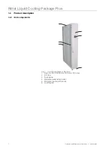
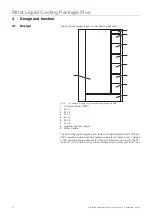
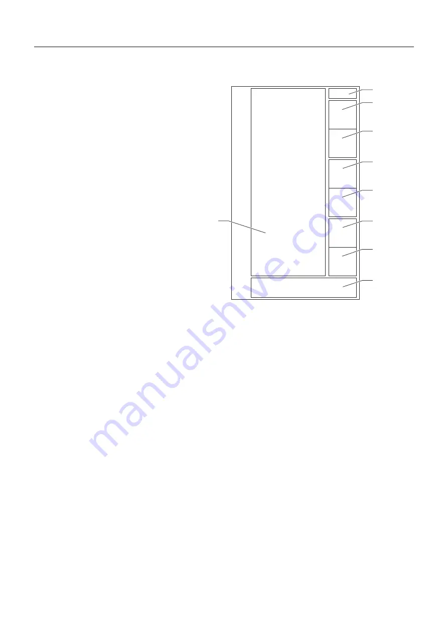
The schematic design is seen in the following illustration:
Fig. 4:
Schematic design of a Liquid Cooling Package Plus
1
Control unit Basic CMC)
2
Fan 1
3
Fan 2
4
Fan 3
5
Fan 4
6
Fan 5
7
Fan 6
8
Air/water heat exchanger
9
Water module
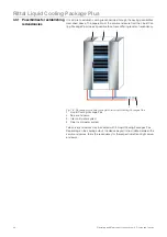
The Liquid Cooling Package Plus consists of a superordinate control unit (Basic
CMC), a water module, a heat exchanger, and six fan modules. Fans, in groups
of two, and the water module contain their own electronic controls (3 x RLCP
fan and 1 x RLCP water), which are connected to one another over an I2C bus.
4
6
9
8
2
3
5
7
1

