16
Operating and Maintenance Instructions – 4 Design and function
Rittal Liquid Cooling Package Plus
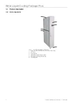
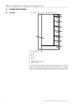
The front door completely seals the Liquid Cooling Package Plus. The graphi-
cal display (touchscreen) for operation in stand-alone mode is located on the
front. Behind the display is a partitioning plate that closes off the cold air section
to the front. The door on the rear side of the device only seals off the Liquid Coo-
ling Package Plus in the upper section of the device. The lower section is co-
vered with a U-shaped plate. The possible connection line to the cold water
network and the condensate discharge hoses are run out of the Liquid Cooling
Package Plus through the resulting opening.
4.1.2 Air/water heat exchanger
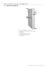
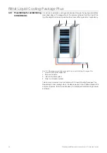
The air/water heat exchanger is installed in the front section of the Liquid Coo-
ling Package Plus between both of the front wall plates. The heat exchanger is
covered with a spray eliminator on the air outlet side that catches any occurring
condensate and directs it to the condensate collecting tray in the Liquid Coo-
ling Package Plus. Three temperature sensors are mounted on the front side of
the spray eliminator at the level of the fan modules. The sensors record the tem-
perature of the cold air that is blown in (server-in temperature) and transfer it to
the control.
4.1.3 Fan module
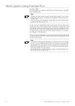
Fig. 7:
Fan module
1
Fan
2
Rack-mounted shelf
3
Control unit for fan module (RLCP fan)
4
T handle
A fan module consists essentially of one fan that is mounted an angle bracket.
One control unit (RLCP fan) controls two fan modules. The fans may be opera-
ted at four output levels and are activated by four relays. (Both fans always ope-
rate at the same output level.)
The fan modules are installed on rack-mounted shelves in the rear section of
the Liquid Cooling Package Plus with the control unit in between. Each shelf
has slide rails on the longitudinal sides. The angle brackets with the fans are
inserted into and held in the rails.
1
2
3
4


