51
Operating and Maintenance Instructions – 6 Installation – "Getting Started"
Rittal Liquid Cooling Package Plus
6.6
Operation
6.6.1 General
A Basic CMC forms the control unit of the Liquid Cooling Package Plus. Its jobs
are to:
- Retrieve all measurements over the I
2
C bus from the fan modules and the wa-
ter module (temperature, speed, flow, etc.).
- Evaluate all measurements and generate alarm and warning signals.
- Calculate the thermal output of the flow and return temperature as well as de-
termine the water flow volume.
- Control air temperature in the server enclosure by regulating the fan speed
and the water volume through the heat exchanger.
- Set the setpoint temperature for the cold air blown in (factory setting 20 °C).
- Control a graphical display (touchscreen) over a RS-232 interface.
- Display the measurements and settings of parameters and setpoints over the
web interface of the CMC.
- Poll the sensor and setting values over SNMP.
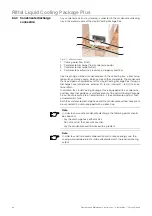
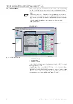
Fig. 45:
Control unit Liquid Cooling Package (Basic CMC) – front
1
Button "C"
2
Status LED (alarms and warnings)
3
Status LED (network status)
4
Hyperterminal
The control unit polls all measurements from the connected fan modules and
water module. This communication takes place over the I
2
C bus. The control
unit thus serves as the master and polls the measurements from the slave units
or returns the setting data.
The measurements which are delivered from the individual modules are evalu-
ated by the control unit and possible warning and alarm signals are generated.
If a new warning or alarm occurs, the internal beeper communicates this. At the
same time, the alarm relay is switched. This acoustic alarm may be cleared by
pressing down the clear button "C" briefly. At the same time, the alarm relay is
reset. The exact cause of malfunction can be displayed in plain text on the con-
nected graphical display (touchscreen). The following messages can be dis-
played:
Warning messages
- Fan speed of fan 1 or 2 from fan unit 1 faulty
- Fan speed of fan 1 or 2 from fan unit 2 faulty
- Fan speed of fan 1 or 2 from fan unit 3 faulty
- Flow faulty
- Control valve faulty
Note:
Further explanations concerning the various setting options and features are
available in the CMC-TC system documentation.
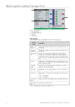
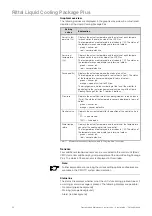
CMC - TC
!
C
Basic CMC
IOIOI
1
2
3
4

