background image

10

Assembly instructions Rittal air/air heat exchangers

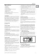
6.3 Changeover °C/°F

Press the Set key for 5 sec. to activate the setting mode. Hold the 
K1 or K2 key down until “PS” appears; confirm by pressing “Set”. 
Enter the code “22” to change from °C to °F in level “/5” (0 = °C 
and 1 = °F). Keep the Set key held down for 5 sec. to save any 
changes. 

6.4 Changing the switching hysteresis

Press the Set key for 5 sec. to activate the setting mode. Hold the 
K1 or K2 key down until “PS” appears; confirm by pressing “Set”.
Enter the code “22” to change the switching hysteresis in level 
“P1”.

6.5 Programming

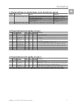
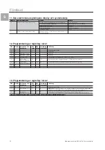
(see diagram 12.1 Programming)

In the EEPROM of the controller various parameters are stored 
which can be changed by using the buttons H2, H3 and H4.
5 changeable parameters can be set in the stated ranges 
(max. and min. values; see diagram 12.1).
The H2, H3 and H4 keys are multiple occupancy. To access pro-
gramming mode, “Set” is to be pressed and held down for 5 sec.

6.6  System message equipment

All system messages at the heat exchanger are recorded and 
displayed as an error number by H1. System messages alternate 
in the display with the current internal enclosure temperature 
(see 11. Display screen and system analysis of electronic control).

6.7 System message contact (K1; potential-free)

The relay is normally closed. All system messages assigned to the 
relay result in it opening. If the control voltage fails, this also results 
in the relay opening. Terminal strip X1 provides the connection, 
see Wiring diagram. K1 fault signal relay (NO contact/changeover 
contact):
Terminal 3: NC (normally closed)
Terminal 4: C (connection between voltage supply and fault 

signal relay)

Terminal 5: NO (normally open)
The definitions NC and NO refer to the deenergised state.

7. Supplementary functions

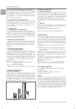
Filter mat use and changing

The PU foam filter mat available as an accessory is coarse and fil-
ters large dust particles or fluff from the air. Metallic filter mats are 
used to trap oil condensation. These are also available as an ac-
cessory. Subject to the suction of the blower being high enough, 
fine dust is blown through the filter mat and the external circuit of 
the unit. This does not affect the unit’s operation.

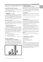
Fig. 7.1  Filter mat replacement

8. Technical information

8.1  Condensation discharge

When operating the air/air heat exchanger in surroundings, in 
which, for example, there is oil/spray mist or high air humidity 
present, these can be condensed in the unit’s external circuit. You 
merely have to remove the plastic stopper fitted to the bottom of 
the enclosure in order to drain it off (Note: only the left hand stop-
per of the two plastic stoppers can be removed in the case of a 
SK 3126.100 unit, as otherwise the protection rating will be lost!)

8.2  General information

Storage temperature: The air/air heat exchangers must not be ex-
posed to temperatures above +70°C.
Disposal can be carried out at the Rittal factory.

Technical modifications reserved.

9. Maintenance

The maintenance-free fans fitted in the unit have sealed ball-bear-
ings and are therefore protected against dust and humidity. The 
life expectancy is at least 30,000 operating hours. The air/air heat 
exchanger is thus largely maintenance free. It is merely the lamel-
la in the heat exchanger cassette that have to be cleaned from 
time-to-time. This can be done by:
a) using compressed air to blow the dry dust off of them 
b) using a detergent solution (max. 75°C) to wash off any grease 

or oil residue (ensure that all sides are dry before refitting!).

The heat exchanger cassette can be removed from the enclosure 
for cleaning by undoing the two eccentric screws. The louvred 
grille and the front plates must have been unscrewed previously 
so that this can be done.
The use of a filter mat is recommended only if large particles of lint 
are present in the air, so that blockage of the heat exchanger is 
prevented (Fig. 7.1 Filter mat replacement).

Attention!

Prior to any maintenance work, the power to the heat exchanger 
unit must be disconnected.

10. Scope of supply and guarantee

1 x air/air heat exchanger ready for connection
1 x drilling template
1 x sealing tape
1 x set of mounting and operating instructions
1 x plug-in terminal strip

Guarantee:

This unit is covered by a 2-year guarantee from the date of supply, 
subject to correct usage (see Safety notices in Section 4 as well). 
Within this period, the returned unit will be repaired in the factory 
or replaced free of charge. The air/air heat exchanger is to be 
used for the cooling of enclosures only. Unauthorised utilisation or 
incorrect connecting up will invalidate the manufacturer’s guaran-
tee. No liability will be assumed for any damage arising from such 
occasions.

Notes

GB

Summary of Contents for SK 3126.100

Page 1: ...es de montaje R RITTAL TOP THERM Luft Luft Wärmetauscher Luft Luft Wärmetauscher Air air heat exchangers Echangeurs thermiques air air Lucht lucht warmtewisselaars Luft luft värmeväxlare Scambiatori di calore aria aria Intercambiadores de calor aire aire SK 3126 100 SK 3127 100 SK 3128 100 SK 3129 100 SK 3130 100 xx xx xx xx xx ...

Page 2: ...2x 266 25 492 518 550 280 550 150 42 108 Montageausschnitt Teileinbau Mounting cut out for partial internal mounting Découpe pour montage partiellement intégré Montage uitsparing gedeeltelijke inbouw Montageavsnitt delinbyggnad Montaggio semincassato Escotadura para montaje interior parcial Abb 3 1 Fig 3 1 Fig 3 1 Afb 3 1 Bild 3 1 Fig 3 1 Fig 3 1 Anbau External mounting Montage en saillie Aanbouw ...

Page 3: ...sparing aanbouw Montageavsnitt påbyggnad Montaggio sporgente Escotadura para montaje exterior Abb 3 1 Fig 3 1 Fig 3 1 Afb 3 1 Bild 3 1 Fig 3 1 Fig 3 1 Montageausschnitt Einbau Mounting cut out for internal mounting Découpe pour montage partiellement intégré Montage uitsparing inbouw Montageavsnitt inbyggnad Montaggio incassato Escotadura para montaje interior Anbau External mounting Montage en sai...

Page 4: ...anbouw Montageavsnitt påbyggnad Montaggio sporgente Escotadura para montaje exterior Abb 3 1 Fig 3 1 Fig 3 1 Afb 3 1 Bild 3 1 Fig 3 1 Fig 3 1 Montageausschnitt Einbau Mounting cut out for internal mounting Découpe pour montage partiellement intégré Montage uitsparing inbouw Montageavsnitt inbyggnad Montaggio incassato Escotadura para montaje interior Anbau External mounting Montage en saillie Aanb...

Page 5: ...vicio Intensidad nominal por ventilador Rendimiento por ventilador Potencia térmica específica Rendimiento de aire de los ventiladores circuito interior circuito exterior Campo de temperaturas Grado de protección Circuito interior Dimensiones anch x alt x prof mm Peso 3126 100 RAL 7035 230 V 50 60 Hz 0 11 A 0 13 A 23 W 27 W 17 5 W K 265 m3 h 315 m3 h 5 55 C EN 60 529 IP 54 280 x 550 x 150 10 kg 312...

Page 6: ...sschnitt für die Luftansaugung möglichst im oberen Bereich des Schaltschrankes befinden sollte die auf dem Typenschild des Gerätes angegebenen Netzan schlussdaten gewährleistet sind die Umgebungstemperatur nicht höher als 55 C ist die Verpackung keine Beschädigungen aufweist Verpackungsschaden kann die Ursache für einen nachfolgen den Funktionsausfall sein der Schaltschrank allseitig abgedichtet i...

Page 7: ... die hohe Ansaugleistung des Gebläses durch die Filtermatte und den Außenkreislauf des Gerätes hindurchgebla sen Die Gerätefunktion wird dadurch nicht beeinflusst Abb 7 1 Filtermattenwechsel 8 Technische Information 8 1 Kondensatablauf Beim Betrieb der LLWT in Umgebungen in denen z B Öl Farb nebel oder hohe Luftfeuchtigkeiten vorhanden sind können sich diese im Außenkreislauf des Gerätes niedersch...

Page 8: ...rt 7 r8 Reset r6 und r7 0 1 Zurücksetzen der Messwerte Tu max und Tu min 8 AL Grenzwert Untertemperatur Ti 50 AH 50 Unterer Grenzwert der zulässigen Schaltschrank Innentemperatur 9 AH Grenzwert Übertemperatur Ti AL 150 40 Oberer Grenzwert der zulässigen Schaltschrank Innentemperatur 10 H5 11 PS 13 Programmierung der Regelung in Ebene 2 Ebene Display anzeige Veränderbare Parameter Min Wert Max Wert...

Page 9: ... excessive dirt and moisture The cut out for air extraction is located in the upper area of the enclosure The mains connection ratings as stated on the rating plate are available The ambient temperature does not exceed 55 C The packing must not show signs of damage Any damage to the packaging may be the cause of subsequent malfunctions The enclosure is sealed on all sides IP 54 The separation of t...

Page 10: ...ndensation discharge When operating the air air heat exchanger in surroundings in which for example there is oil spray mist or high air humidity present these can be condensed in the unit s external circuit You merely have to remove the plastic stopper fitted to the bottom of the enclosure in order to drain it off Note only the left hand stop per of the two plastic stoppers can be removed in the c...

Page 11: ...asured value 7 r8 Reset r6 and r7 0 1 Resetting the measured values Tu max and Tu min 8 AL Limit value min temperature Ti 50 AH 50 Lower limit value of admissible enclosure internal temperature 9 AH Limit value max temperature Ti AL 150 40 Upper limit value of admissible enclosure internal temperature 10 H5 11 PS 13 Control programming in level 2 Level Display screen Changeable parameter Min value...

Page 12: ... présente aucune concentration de poussière et d humidité La fente d aspiration de l air se trouve si possible dans la partie supérieure de l armoire électrique Les caractéristiques de branchement données sur la plaque si gnalétique sont respectées La température ambiante n est pas supérieure à 55 C L emballage ne présente pas de dommage Les altérations de l emballage peuvent être la cause de l un...

Page 13: ...l n en est pas affecté Fig 7 1 Echange de tissu de filtre 8 Information technique 8 1 Evacuation de condensation Dans les milieux présentant par exemple une forte concentration de brouillard d huile et d humidité de l air le fonctionnement des échangeurs thermiques air air peut provoquer la condensation sur le circuit extérieur Pour exécuter la vidange du carter il suffit de dévisser les bouchons ...

Page 14: ...max Valeur mesurée 6 r7 Valeur mesurée Tu min Valeur mesurée 7 r8 Reset r6 et r7 0 1 Réinitialiser les valeurs mesurées Tu max et Tu min 8 AL Valeur sous température Ti 50 AH 50 Limite inférieure de la température intérieure de l armoire 9 AH Valeur sur température Ti AL 150 40 Limite supérieure de la température intérieure de l armoire 10 H5 11 PS 13 Programmation de la régulation sur le niveau 2...

Page 15: ...zich in het bovenste deel van de behuizing bevindt de op het typeplaatje van het apparaat aangegeven netaansl uitgegevens corresponderen met de aanwezige netspanning de omgevingstemperatuur niet hoger is dan 55 C de verpakking niet is beschadigd Elke verpakkingsschade kan de oorzaak zijn van een latere storing de behuizing aan alle kanten is afgedicht IP 54 de afstand tussen de apparaten onderling...

Page 16: ... apparaat geblazen Deze deeltjes beïnvloeden de wer king van het apparaat niet Afb 7 1 Filtermat vervangen 8 Technische informatie 8 1 Condensafvoer Bij inzet van de LLWW in omgevingen waarin b v olie verfnevel of een hoge luchtvochtigheid voorkomt kan afzetting of condens vorming in het externe circuit van het apparaat optreden Voor het aftappen uit de kast kan gewoon de plastic stop aan de onder...

Page 17: ...7 0 1 Resetten van de meetwaarden Tu max en Tu min 8 AL Grenswaarde te lage temperatuur Ti 50 AH 50 Onderste grenswaarde van de toelaatbare behuizingsbinnentemperatuur 9 AH Grenswaarde te hoge temperatuur Ti AL 150 40 Bovenste grenswaarde van de toelaatbare behuizingsbinnentemperatuur 10 H5 11 PS 13 Programmering van de regeling in niveau 2 Niveau Display melding Instelbare parameters Min waarde M...

Page 18: ... IP 54 Avståndet mellan två aggregat och avståndet till väggen ska vara minst 200 mm Luftin och utgång får inte byggas för på insidan Aggregaten skall placeras vågrätt motsvarande det föreskrivna läget Den elektriska anslutningen och eventuella reparationer får endast göras av auktoriserad fackpersonal Använd bara origi nalreservdelar Förlusteffekten för de i kopplingsskåpet installerade kompo nen...

Page 19: ...as inte därigenom Bild 7 1 Byte av filtermatta 8 Teknisk information 8 1 Kondensavledning Vid drift av kylaggregaten i omgivningar i vilka t ex olje färg dimma eller hög luftfuktighet finns kan denna slå sig ner i det yttret kretsloppet till aggregatet För avtappning ur lådan kan helt enkelt plastproppen tas ur lådbotten anmärkning för aggregatet SK 3126 100 får endast den vänstra av de båda plast...

Page 20: ...rde 7 r8 Reset r6 och r7 0 1 Återställning av mätvärdena Tu max och Tu min 8 AL Gränsvärde lägsta temperatur Ti 50 AH 50 Lägsta gränsvärde för apparatskåpets tillåtna innertemperatur 9 AH Gränsvärde högsta temperatur AL 150 40 Högsta gränsvärde för apparatskåpets tillåtna innertemperatur 10 H5 11 PS 13 Programmering av reglering i nivå 2 Nivå Display Parametrar som kan ändras Min värde Max värde I...

Page 21: ...ll aria si trovino possibilmente nella parte alta dell armadio che la rete di allacciamento sia idonea alle caratteristiche riportate sulla targhetta dell apparecchio che la temperatura dell ambiente non superi i 55 C l imballo non presenti danni dovuti al trasporto Ogni dan neggiamento dell imballo può causare successivi guasti compromettendo il buon funzionamento del condizionatore l armadio sia...

Page 22: ...apparecchio stesso Perciò il funzionamento dell apparecchio non viene compromesso Fig 7 1 Sostituzione del filtro 8 Informazioni tecniche 8 1 Scarico della condensa Durante il funzionamento dello scambiatore di calore aria aria nel quale sono presenti ad es nebbia d olio di colore questi ultimi possono condensare nel circuito esterno dell apparecchio Per lo scarico dalla calotta il tappo in plasti...

Page 23: ... Non rilevante 5 r6 Valore Tu max Valore 6 r7 Valore Tu min Valore 7 r8 Reset r6 e r7 0 1 Reset dei valori Tu max e Tu min 8 AL Valore minimo di temperatura Ti 50 AH 50 Valore minimo della temperatura interna all armadio 9 AH Valore di sovra temperatura Ti AL 150 40 Valore massimo della temperatura interna all armadio 10 H5 11 PS 13 Programmazione della regolazione nel livello di menu 2 Livelli In...

Page 24: ...e red coincida con la indicada en la placa de características del aparato que la temperatura ambiente no supere los 55 C que el embalaje no presente desperfectos Todo desperfecto en el embalaje puede ser causa de un fallo de funcionamiento posterior que el armario mantenga una estanqueidad adecuada IP 54 que la distancia entre las unidades o entre la unidad y la pared sea como mínimo de 200 mm que...

Page 25: ...vés de la estera filtrante y el circuito exterior del aparato No influye en el buen funcionamiento del aparato Figura 7 1 Sustitución de la estera filtrante 8 Información técnica 8 1 Eliminación del agua de condensación Al utilizar los intercambiadores en ambientes que presentan nie bla de aceite pintura o altos niveles de humedad del aire éstos pueden afectar el circuito exterior del aparato Para...

Page 26: ...n relevancia 5 r6 Valor de medición Tu max Valor de medición 6 r7 Valor de medición Tu min Valor de medición 7 r8 Reset r6 y r7 0 1 Reset de los valores medidos Tu max y Tu min 8 AL Valor límite Temperatura mínima Ti 50 AH 50 Valor límite mínimo de la temperatura interior del armario admisible 9 AH Valor límite Temperatura máxima Ti Ti AL 150 40 Valor límite máximo de la temperatura interior del a...

Page 27: ...e de température intérieure Aansluitschema C2 C4 Bedrijfscondensatoren F1 Thermostaat M2 Ventilator extern circuit M4 Ventilator intern circuit X1 Aansluitklemmenstrook A1 Hoofdstroomprint A2 Display B1 Temperatuursensor binnentemp Anslutningsschema C2 C4 Startkondensator F1 Termostat M2 Fläkt M4 Fläkt X1 Huvudkontaktplint A1 Drivkort A2 Display terminal B1 Temperaturgivare innertemperatur Schema ...

Page 28: ...ción 5 Außenkreislauf ventilator External circuit fan Ventilateur de circuit extérieur Ventilator extern circuit Fläkt yttre kretslopp Ventilatore circuito esterno Ventilador del circuito exterior 10 Innenkreislauf ventilator Internal circuit fan Ventilateur de circuit intérieur Ventilator intern circuit Fläkt inre kretslopp Ventilatore circuito interno Ventilador del circuito interior 15 Versandb...

Page 29: ...Montageanleitung Rittal Luft Luft Wärmetauscher 29 40 15 5 100 71 55 45 75 10 SK 3126 100 71 10 75 40 100 75 45 50 45 55 5 15 SK 3127 100 SK 3128 100 SK 3129 100 ...

Page 30: ...30 Montageanleitung Rittal Luft Luft Wärmetauscher 55 45 71 10 15 75 40 100 75 50 55 46 45 46 5 SK 3130 100 ...

Page 31: ...Paramètres 2 Diagram 12 1 Programmering Gewenste waarde 1 Parameters 2 Diagram 12 1 Programering Börvärde 1 Parametrar 2 Diagramma 12 1 Programmazione Impostazione valori 1 Parametri 2 Diagrama 12 1 Programación Ajuste 1 Parámetros 2 K1 K2 K1 K2 K1 K2 K1 K2 K1 K2 K1 K2 K1 K2 K1 K2 K1 K1 K2 K2 K1 K2 K1 2 sec K1 2 sec 1 K1 K2 K1 K2 K1 K2 K1 K2 K1 K2 K1 K2 K1 K2 K1 K2 K1 K2 5 sec 5 sec K1 K2 K1 K2 K2...

Page 32: ...imate Control Climatisation Systeemklimatisering Systemklimatisering Soluzioni di climatizzazione Climatización de sistemas Schaltschrank Systeme Industrial Enclosures Coffrets et armoires électriques Kastsystemen Apparatskåpssystem Armadi per quadri di comando Sistemas de armarios Elektronik Aufbau Systeme Electronic Packaging Electronique Electronic Packaging Systems Electronic Packaging Conteni...

Reviews: