Rittal enclosure cooling unit
23
5 Installation
EN
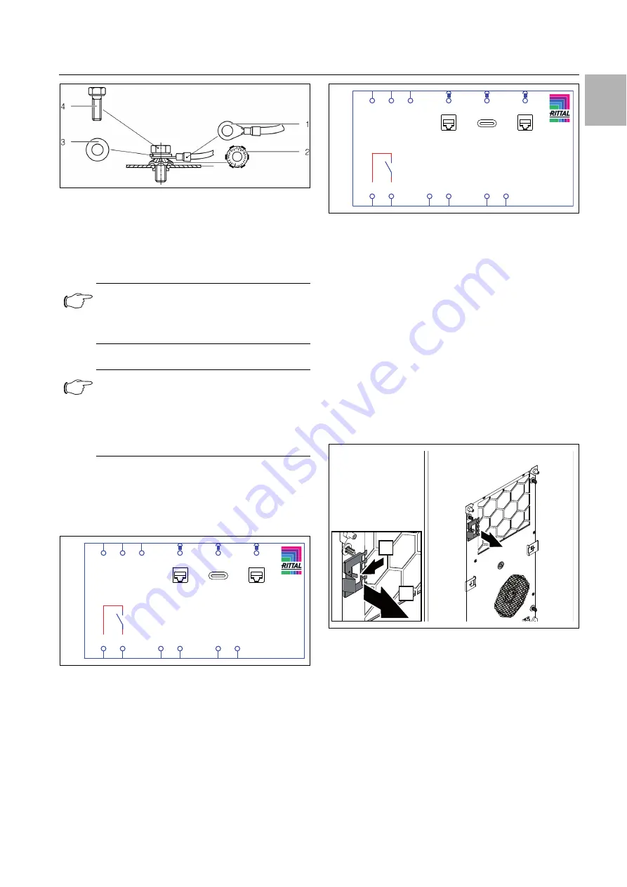
Fig. 44:
Potential equalisation arrangement
Key
1
Ring terminal with PE conductor
2
Contact washer
3
Washer
4
Screw
5.4.2
Install the power supply
Remove the mains connector from the dispatch bag
and connect to the mains as shown on the connection
diagram (fig. 45 or fig. 46).
Use copper conductors only to connect the supply ca-
ble to the mains connector.
Fig. 45:
Circuit diagram SK 3178800, SK 3178801,
SK 3179800, SK 3179801, SK 3184800
Fig. 46:
Circuit diagram SK 3184840
Key
X1
Main terminal strip
K1
Alarm relay
Door Door limit switch (optional, without door limit switch: ter-
minal 5, 6 open)
NTC External temperature sensor (optional)
X2
RS 485 interface
X4
USB-C interface
X5
Rittal Smart Service Portal (LAN)
Attachment option for cable routing
By moving a locator clip and connecting it to the rear of
the device near the electrical connections, it can be used
as a cable attachment.
Depending on the type of installation, remove the loca-
tor clip from the front (internal mounting) or rear (exter-
nal mounting) of the unit.
Fig. 47:
Removing the locator clips from the front of the device
with the installation type "internal mounting" (sample il-
lustration)
Note:
According to the standard, the PE conductor
in the mains connection cable is not classed
as an equipotential bonding conductor.
Note:
– We recommend that the power supply ca-
ble and the signal cable should be of a
shielded design.
– The cable shield can be contacted at the
potential equalisation point (fig. 43).
Alarm
Door
NTC
K1
BUS
USB-C
LAN
-EC1
L1
X1
2
COM
X3
3
NO
PE
L2/N
6
5
X3
8
7
X3
1-9
RS-485
X2
1-24
USB-C
X4
1-9
LAN
X5
Alarm
Door
NTC
K1
BUS
USB-C
LAN
-EC1
L1
X1
2
COM
X3
3
NO
PE
L2
6
5
X3
8
7
X3
1-9
RS-485
X2
1-24
USB-C
X4
1-9
LAN
X5
1.
2.


