5 Installation
EN
24
Rittal enclosure cooling unit
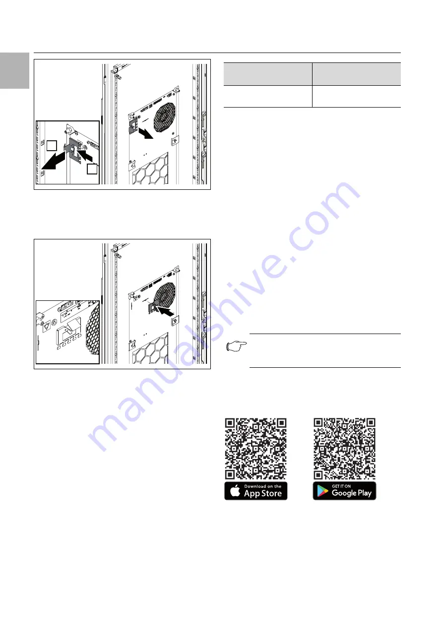
Fig. 48:
Removing the locator clips from the rear of the device
with the installation type "external mounting" (sample il-
lustration)
Next, insert the locator clips onto the rear of the device
near the electrical connections.
Fig. 49:
Locator clip for cable routing (sample illustration)
Use the locator clips to secure the cables (e.g. using
cable ties).
5.4.3
Connect the alarm relay
System messages from the cooling unit may be output
to an external signal source via a floating relay output.
The relay output is in the de-energised state NO (Nor-
mally Open). As soon as voltage is applied to the cooling
unit, the alarm relay picks up. This is the factory setting
for the cooling unit's normal operating state. As soon as
a system message occurs or the power supply is inter-
rupted, the alarm relay will drop out and open the con-
tact.
The switch logic of the alarm relay can be altered using
the Rittal Scan & Service app (see section 7.5.2 "Config-
uration").
Connect a suitable connection cable to terminal 3
(alarm K1) of the signal connector (X3).
Configure the alarm relay you wish to use to output
system message messages (see section 7.4.8 "Evalu-
ate system messages").
5.4.4
Interfaces
The cooling unit has the following interfaces for commu-
nicating with external systems:
– USB-C interface on the rear
– RS 485 interface on the rear
– NFC interface on the front
– Interface to the Rittal Smart Service Portal (LAN) at the
rear
USB-C interface
An USB-C interface (X4) is located at the rear near the
top. A laptop may be connected here for easy update
(see section 7.3 "Updater program").
Other USB units are not recognized on this connection.
RS 485 interface
An RS 485 interface is located on the rear of the connec-
tion box (X2). The IoT interface for linking the cooling unit
to the customer's own monitoring, energy management
and/or superordinate systems may be connected here.
Connect the IoT interface (accessory) to the RS 485
interface (X3).
NFC interface
You can access the cooling unit with the Rittal Scan &
Service app via the integral NFC interface. Apps other
than those supplied by Rittal are not supported.
Fig. 50:
Download options for the Rittal Scan & Service app
Rittal Smart Service Portal (LAN)
There is a LAN interface (X5) at the rear, which you can
use to connect directly to the Rittal Smart Service Portal.
1.
2.
AC
cos φ = 1
DC
I max. = 2 A
U max. = 250 V
I max. = 2 A
U max. = 30 V
Tab. 4:
Contact data
Note:
A direct connection to the cooling unit via the
RS 485 interface is not possible.


