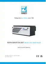
Rittal enclosure cooling unit
37
8 Inspection and maintenance
EN
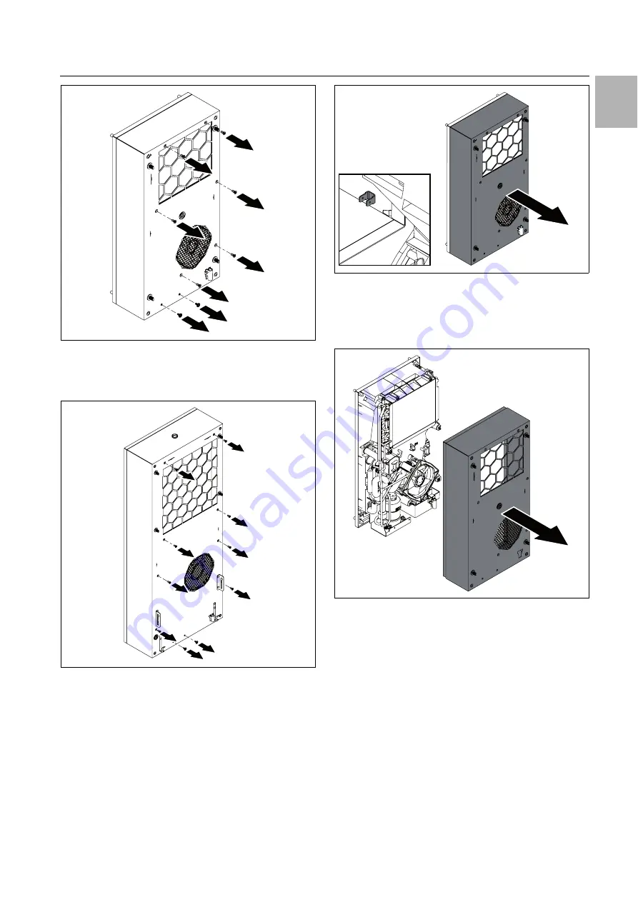
Fig. 59:
Loosen the assembly screws (for SK 317880x and
SK 317980x)
For SK 31848x0: Loosen the ten screws connecting
the cover to the rear panel.
Fig. 60:
Loosen the assembly screws (for SK 31848x0)
Gently pull the cover forwards (approx. 5 cm) away
from the rear panel.
The PE conductor connection between the cover and
the rear panel is located at the bottom left.
Fig. 61:
PE conductor connection (sample illustration)
Disconnect the PE conductor's flat-pin connector
from the inside, preferably on the cover.
Remove the cover completely from the rear panel, and
set or lay it down in a safe place.
Fig. 62:
Remove the cover
Dismantling of the cover is now complete, providing ac-
cess to all components in the external circuit.
8.4.4
Cleaning the components with com-
pressed air
After removing the cover from the unit, you will be able
to access the components in the outer circuit, particu-
larly the condenser, the condenser fan and the com-
pressor chamber.
Wear cut-resistant gloves when cleaning with com-
pressed air, so as to avoid injuries caused by sharp
edges inside the unit.
When cleaning the components with compressed air,
blow dirt sideways out of the cooling unit.
Alternatively, use a suitable vacuum cleaner to clean all
components.


