background image


39


ENTER

ENTER

ENTER

ENTER

°

TEST

ENTER

°

F

(Standard = normal)

(Standard = normal)

Fan

„1“ = continue

„0“ = normal

„1“ = parallel

„0“ = normal

PLC (SPS)

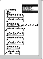
 T = 3.....15 K; (Standard = 5 K)

max. T

i

 = 40.....55 

°

C; (Standard = 45 

°

C)

min. T

i

 = 20.....35 

°

C; (Standard = 30 

°

C)

Code number = 123

Master slave
Code number = 101

(Standard = 

°

C)

„1“ = 

°

F

„0“ = 

°

C

T

i

 = 30.....45

°

C; (Standard = 35

°

C)

T

Filter 

= 4.....40 K; (Standard = off = 99)

0

1

099

004

040

045

036

035

32

9

8

7

6

5

4

3

2

1

10 s

ENTER

ENTER

0

1

ENTER

ENTER

ENTER

ENTER

000

001

123

ENTER

ENTER

0

1

ENTER

ENTER

030

020

025

ENTER

ENTER

045

046

055

ENTER

ENTER

005

006

015

ENTER

101

ENTER

…00

ENTER

50

…01

16

ENTER


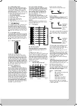
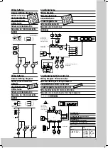
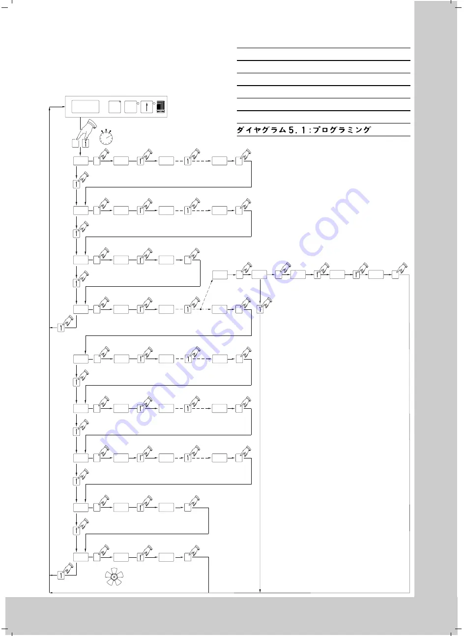
Diagramm 5.1: Programmierung

Diagram 5.1: Programming

Diagramme 5.1: Programmation

Diagram 5.1: Programmering

Diagram 5.1: Programering

Diagramma 5.1: Programmazione

Diagrama 5.1: Programación

Summary of Contents for SK 3260.140

Page 1: ...ld volgens de op het type plaatje aangegeven nominale stroom VARNING Montering av apparatskåpskylaggregat Vid montering måste beaktas att varmluftsintag och kalluftsutblås inte är spärrade En fri luftcirkulation inuti skåpet måste garanteras Utrymmet mellan luftintag utblåsöppningar och installationerna måste vara 200 mm Efter att kylaggregatet stängts av kan det startas först efter 5 minuter Anvä...

Page 2: ...ld volgens de op het type plaatje aangegeven nominale stroom VARNING Montering av apparatskåpskylaggregat Vid montering måste beaktas att varmluftsintag och kalluftsutblås inte är spärrade En fri luftcirkulation inuti skåpet måste garanteras Utrymmet mellan luftintag utblåsöppningar och installationerna måste vara 200 mm Efter att kylaggregatet stängts av kan det startas först efter 5 minuter Anvä...

Page 3: ...1 A 4 6 A 5 8 A 4 A 4 A 100 470 W 520 W 520 W 605 W 825 W 960 W 680 W 720 W R134 a 525 g 25 bar 20 55 C 62 dB A IP 54 IP 34 400 x 950 x 230 38 kg RAL 7032 SK 3281 100 115 V 50 60 Hz 6 5 A 7 6 A 16 4 A 20 1 A 10 A 10 A 100 470 W 520 W 520 W 605 W 825 W 960 W 680 W 720 W R134 a 525 g 25 bar 20 55 C 62 dB A IP 54 IP 34 400 x 950 x 230 38 kg RAL 7032 SK 3393 100 SK 3393 500 230 V 50 60 Hz 4 2 A 4 4 A ...

Page 4: ...g the protective earth conductor high voltage and the insulation in the enclosure 5 Commencing Operation and Control Behaviour Following the completion of mounting and a waiting period of approximately 30 minutes to allow oil to collect in the compressor in order to ensure lubrication and cooling electrical connec tion can be made 5 1 Control by Thermostat Version 100 140 The cooling unit operates...

Page 5: ... e g plain text display which are connected to the PLC or by means of the serial interface to a higher order computer Construction of the PLC interface The construction is potential separated via opto coupler wiring diagram fig 5 4 Connection is made by the customer to the 15 pin socket on the control board fig 5 4 to the PLC input card Attention The electrical signals at the interface are of an e...

Page 6: ... lines are short 6 3 Programming the Cooling Unit See diagram 5 1 for details on programming IDs NOTE Only one unit may be configured as master the address ID must match the number of slave units The individual slave units must have different addresses the addresses must be in ascending order without gaps in between Example 1 master cooling unit with 2 slave cooling units Master cooling unit Slave...

Page 7: ...enclosure temperature Ti 30 45 35 The standard thermostat setting range is 35 45 C The upper and lower limits can be adjusted through programm level 5 and 6 2 Set value of filter mat monitor 4 40 99 off 99 Factory setting is the shut off value 99 To activate 1 Install clean filter mat and let air conditioner cool for a few minutes 2 Select programm level 2 see diagram 5 1 page 39 3 Push test butto...

Page 8: ...n S2 Door limit switch without door operated switch terminal 1 2 open T1 Transformer Electrical Connection by Customer X2 PLC interface Sub D socket 15 pole X10 Terminal strip X10 L1 L2 N PE Mains connection brown L1 phase blue L2 N neutral green yellow PE ground L1 L2 L3 SK 3260 500 X10 1 2 Door operated switch connection supplied by customer X10 3 4 5 Collective fault message Anslutningsschema m...

Page 9: ...ormer see type plate Techn data Kontaktdaten K1 Contact Data K1 Caracteristiques des contacts K1 Kontaktgegevens K1 Kontaktdata K1 Caratteristiche dei contatti K1 Características del contacto K1 AC cosf 1 DC L R 40 ms I max 5 A U max 230 V I min 10 mA U max 100 V I max 200 mA U max 20 V I max 5 A K 1 35 Wirkschaltplan Detailed Wiring Diagram Schéma des con nexions détaillé Werkingsschema Driftsche...

Page 10: ... Lamellengitter 2 Louvred grille 2 Grille à lamelles 2 Rooster 2 Lamellgitter 2 Griglia a lamelle 2 Rejilla 2 46 Lamellengitter 1 Louvred grille 1 Grille à lamelles 1 Rooster 1 Lamellgitter 1 Griglia a lamelle 1 Rejilla 1 50 Abdeckblende Infill panel Couvercle Afdekplaat Täckplåt Copertura cieca Pantalla cubierta 55 Anzeigeplatine Display PCB Platine d indication Displayprint Displaykort Scheda di...

Page 11: ... 55 75 5 71 25 1 30 20 15 35 40 85 80 10 71 SK 3293 XXX 3281 100 3393 XXX 3381 100 SK 3298 100 3298 500 3279 100 3260 XXX 71 25 1 30 15 20 35 40 85 5 45 45 46 50 65 66 55 75 10 71 100 80 100 90 90 70 2 2 70 71 71 48 48 ...

Page 12: ... 25 35 45 55 Kennlinienfeld DIN 3168 Performance Diagram Diagramme des lignes caracteristiques Karakteristik kurva Diagramma delle curve caratteristiche Diagrama de potencia Verflüssigereintritt C Liquifier entry Entrée du condenseur Kondensorinlaat Kondensoringång Ingresso condensatore Entrada del condensador Tu Verdampfereintritt C Evaporator entry Entrée de l évaporateur Verdamperinlaat Förånga...

Page 13: ...i 30 45 C Standard 35 C TFilter 4 40 K Standard off 99 0 1 099 004 040 045 036 035 32 9 8 7 6 5 4 3 2 1 10s ENTER ENTER 0 1 ENTER ENTER ENTER ENTER 000 001 123 ENTER ENTER 0 1 ENTER ENTER 030 020 025 ENTER ENTER 045 046 055 ENTER ENTER 005 006 015 ENTER 101 ENTER 00 ENTER 50 01 16 ENTER Diagramm 5 1 Programmierung Diagram 5 1 Programming Diagramme 5 1 Programmation Diagram 5 1 Programmering Diagra...

Reviews: