
360
920
400
400
950
45
185
100
130
230
13
5
465
950
400
950
15
310
225
385
Ø 7
900
380
320
230
A
320
B
(4 x)
Ø 9.5
(4 x)
Ø 9.5
(4 x)
(8 x)
(4 x)
400
1265
345
300
15
520
225
490
Ø 9.5
1265
400
1235
260
100
160
45
215
400
1265
380
360
320
Ø 7
1215
260
360
450
440
(4 x)
Ø 9.5
M 8 x 30
10 x 8
A 8.4
M 8
SW 13
M 8
SW 13
M 6
SW 13
A 8.4
10 x 4
B 4.8 x 13
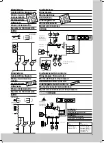
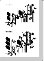
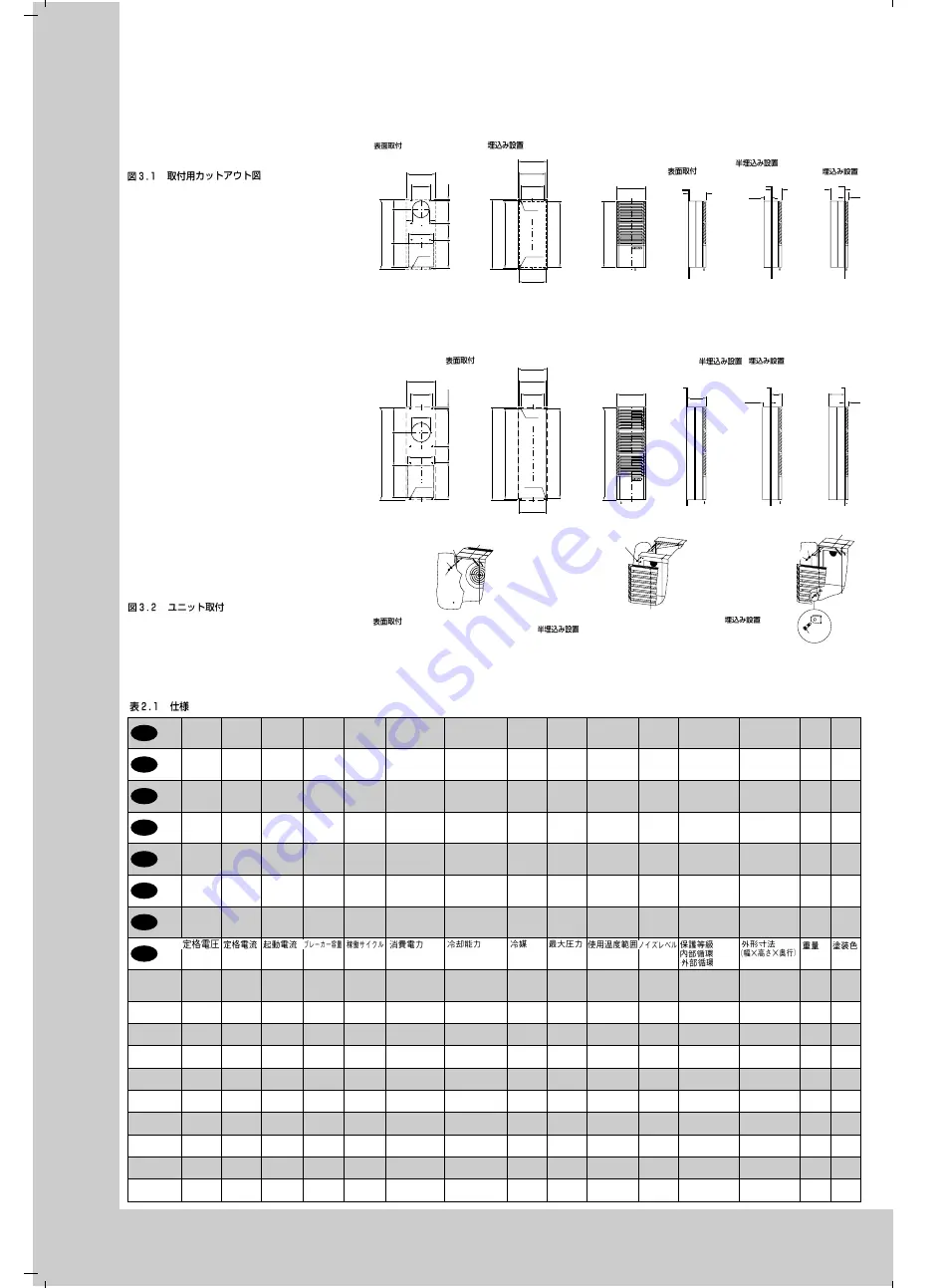
Abb. 3.2
Gerätemontage
Fig. 3.2
Mounting
Fig. 3.2
Montage de l’appareil
Afb. 3.2
Apparaatmontage
Bild 3.2
Aggregatmontage
Fig. 3.2
Montaggio dell’apparecchio
Fig. 3.2
Montaje del aparato
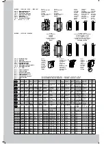
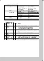
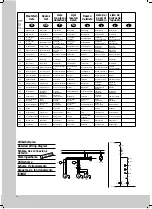
Tab. 2.1
Technische Daten
Tab. 2.1
Technical Data
Tab. 2.1
Données techniques
Tab. 2.1
Technische gegevens
Tab. 2.1
Tekniska data
Tab. 2.1
Caratteristiche tecniche
Tab. 2.1
Datos técnicos
Betriebs-
spannung
Nenn-
strom
Anlauf-
strom
Vorsiche-
rung T
Einschalt-
dauer
Nennleistung
Nutzkühlleistung Kältemittel zul.
Betriebs-
überdruck
Temperatur-
bereich
Geräusch-
pegel
Schutzart
Innenkreislauf
Außenkreislauf
Abmessungen
(B x H x T)
mm
Gewicht Farbton
Operating
voltage
Rated
current
Starting
current
Pre-fuse
T
Duty cycle Power
consumption
Useful cooling
output
Refrigerant Permis-
sible
pressure
Temperature
range
Noise
level
Protection categ.
Internal circuit
External circuit
Dimensions
(W x H x D)
mm
Weight Colour
Tension
nominale
Courant
nominal
Courant de
démarrage
Dispositif
de sécurité
T
Durée de
mise en
circuit
Puissance
nominale
Puissance
frigorifique
de rég.
Fluide
frigori-
gène
Pression
de régime
autor.
Plage de
température
Niveau
sonore
Degré de protect.
Circuit intérieur
Circuit extérieur
Dimensions
(L x H x P)
mm
Poids
Coloris
Bedrijfs-
spanning
Nominale
stroom
Aanloop-
stroom
Primaire
zekering T
Inschakel-
duur
Nominaal
vermogen
Nuttig
koelvermogen
Koel-
middel
p. max.
Temperatuur-
bereik
Geluids-
nivo
Beschermklasse
Inwendig circuit
Uitwend. circuit
Afmetingen
(B x H x D)
mm
Gewicht Kleur
Anslut-
nings-
spänning
Märk-
ström
Startström Försäkring
gL
Inkopp-
lingstid
Märkeffekt
Effektiv
kyleffekt
Kylmedel
Tillåtet
drifts-
övertryck
Temperatur-
område
Ljudnivå
Kapslingsklass
Inre kretslopp
Yttre kretslopp
Mått
(B x H x D)
mm
Vikt
Färgton
Tensione
nominale
Corrente
nominale
Corrente
di spunto
Fusibili T
Ciclo d’in-
serzione
Potenza
nominale
Potenza
frigorifera utile
Fluido
frigorigeno
Pressione
max.
Campo di
temperatura
Livello
di rumore
Grado di protez.
Circuito interno
Circuito esterno
Dimensioni
(L x A x P)
mm
Peso
Colore
Tensión
de
servicio
Intensidad
nominal
Intensidad
de
arranque
Fusible T
Duración
de
conexión
Potencia
nominal
Potencia
frigorífica útil
Fluido
frigorífico
Presión
máxima
admis.
Campo de
temperaturas
Nivel
de ruido
Protección
Circuito interior
Circuito exterior
Dimensiones
(anch. x alt.
x prof.) mm
Peso
Color
L35 L35
L35 L50
DIN 3168/EN 814
L35 L35
L35 L50
EN 60 529
SK 3293.100
SK 3293.500
230 V,
50/60 Hz
3.1 A/
3.6 A
8.5 A/
10.0 A
6 A/
6 A
100%
450 W/500 W
500 W/580 W
825 W/960 W
680 W/720 W
R134 a,
525 g
25 bar
+ 20 –
+ 55
°
C
62 dB (A)
IP 54
IP 34
400 x 950 x 230 35 kg
RAL
7032
SK 3293.140
SK 3293.540
400 V,
50/60 Hz
1.8 A/
2.1 A
4.6 A/
5.8 A
4 A/
4 A
100%
470 W/520 W
520 W/605 W
825 W/960 W
680 W/720 W
R134 a,
525 g
25 bar
+ 20 –
+ 55
°
C
62 dB (A)
IP 54
IP 34
400 x 950 x 230 38 kg
RAL
7032
SK 3281.100
115 V,
50/60 Hz
6.5 A/
7.6 A
16.4 A/
20.1 A
10 A/
10 A
100%
470 W/520 W
520 W/605 W
825 W/960 W
680 W/720 W
R134 a,
525 g
25 bar
+ 20 –
+ 55
°
C
62 dB (A)
IP 54
IP 34
400 x 950 x 230 38 kg
RAL
7032
SK 3393.100
SK 3393.500
230 V,
50/60 Hz
4.2 A/
4.4 A
9.8 A/
11.4 A
6 A/
6 A
100%
590 W/660 W
670 W/750 W
1100 W/1150 W
830 W/850 W
R134 a,
550 g
24 bar
+ 20 –
+ 55
°
C
62 dB (A)
IP 54
IP 34
400 x 950 x 230 38 kg
RAL
7032
SK 3393.140
SK 3393.540
400 V,
50/60 Hz
2.5 A/
2.6 A
5.7 A/
6.6 A
6 A/
6 A
100%
610 W/680 W
690 W/780 W
1100 W/1150 W
830 W/850 W
R134 a,
550 g
24 bar
+ 20 –
+ 55
°
C
62 dB (A)
IP 54
IP 34
400 x 950 x 230 41 kg
RAL
7032
SK 3381.100
115 V,
50/60 Hz
8.6 A/
9.2 A
19.8 A/
23.1 A
10 A/
10 A
100%
610 W/680 W
690 W/780 W
1100 W/1150 W
830 W/850 W
R134 a,
550 g
24 bar
+ 20 –
+ 55
°
C
62 dB (A)
IP 54
IP 34
400 x 950 x 230 41 kg
RAL
7032
SK 3298.100
SK 3298.500
230 V,
50/60 Hz
5.5 A/
5.7 A
17.5 A/
16.5 A
10 A/
10 A
100%
830 W/1040 W
940 W/1170 W
1400 W/1450 W
1100 W/1150 W
R134 a,
525 g
25 bar
+ 20 –
+ 55
°
C
62 dB (A)
IP 54
IP 34
400 x 1265 x 260 48 kg
RAL
7032
SK 3279.100
115 V,
50/60 Hz
11.5 A/
12.0 A
36.0 A/
37.0 A
16 A/
16 A
100%
860 W/1080 W
975 W/1210 W
1400 W/1450 W
1100 W/1150 W
R134 a,
525 g
25 bar
+ 20 –
+ 55
°
C
62 dB (A)
IP 54
IP 34
400 x 1265 x 260 51 kg
RAL
7032
SK 3260.500
SK 3260.140
400 V– 3 ~
50/60 Hz
2.3 A/
2.6 A
9.5 A/
9.5 A
6 A/
6 A
100%
900 W/750 W
1060 W/920 W
1740 W/1630 W
1340 W/1220 W
R134 a,
525 g
24 bar
+ 20 –
+ 55
°
C
65 dB (A)
IP 54
IP 34
400 x 1265 x 260 60 kg
RAL
7032
D
GB
F
NL
S
I
E
J
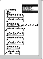
SK 3293. . . . / 3281.100 / 3393. . . . / 3381.100*
Abb. 3.1
Montageausschnitte
Fig. 3.1
Mounting Cut-out
Fig. 3.1
Découpe de montage
Afb. 3.1
Montage-uitsparingen
Bild 3.1
Håltagning
Fig. 3.1
Dime di foratura
Fig. 3.1
Recorte del montaje
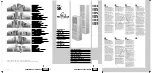
SK 3298. . . . / 3279.100 / 3260.500
Anbau
Einbau
External Installation
Internal Installation
Implanté
Intégré
Aanbouw
Inbouw
Utanpå
Inbyggnad
Montaggio sporgente
Montaggio incassato
Montaje exterior
Montaje interior
Anbau
External
Installation
Implanté
Aanbouw
Utanpå
Montaggio
sporgente
Montaje
exterior
Anbau
External Installation
Implanté
Aanbouw
Utanpå
Montaggio sporgente
Montaje exterior
Teileinbau, Einbau
Internal or Partially Internal Installation
Partiellement intégré, intégré
Inbouw
Delvis inbyggnad, inbyggnad
Montaggio semincassato o incassato
Montaje parcial, montaje interior
,
Anbau
External
Installation
Implanté
Aanbouw
Utanpå
Montaggio
sporgente
Montaje
exterior
* Nur für 400 mm tiefe PS/ES Schränke SK 3393. . . . / 338.1100, A = 250 mm, B = 300 mm
Nur für Schränke über 400 mm Tiefe SK 3393. . . . / 338.1100 A = 250 mm, B = 340 mm
Nur für Schränke über 400 mm Tiefe SK 3293. . . . / 328.1100 A = 300 mm, B = 340 mm
Teileinbau
Partially Internal
Installation
Partiellement
intégré
Gedeeltelijke
inbouw
Delvis inbyggnad
Montaggio
semincassato
Montaje parcial
Einbau
Internal
Installation
Intégré
Inbouw
Inbyggnad
Montaggio
incassato
Montaje
interior
Teileinbau
Partially
Installation
Partiellement Intégré
Gedeeltelijke inbouw
Delvis inbyggnad
Montaggio
semincass.
Montaje parcial
Einbau
Internal
Installation
Intégre
Inbouw
Inbyggnad
Montaggio
incassato
Montaje
interior


