
7
5.2.3 Fault Signalling Facility
All faults on the cooling unit are registered and
indicated by H1 as a fault number. The display is
by means of the left-hand number. The display
cycles through all pending fault messages in a
2 second cycle, starting with the internal tempera-
ture of the enclosure.
H1 indicates the following faults as a fault number.
1 = Enclosure internal temperature too high
(5 K above setpoint value)
2 = Current monitor, condenser
3 = Evaporator (no collective fault indication).
4 = High-pressure monitor
5 = Current monitor, condenser fan
6 = Current monitor, evaporator fan
7 = Filter mat soiled
8 = Temperature sensor cable break/short-circuit
5.2.3.1 Fault Signal Contact
(K1, potential-free)
The fault signal relay is pulled in at normal condi-
tion. Any faults will cause the relay to drop out
(except low-pressure monitor, fault number 3).
Any failure of the control voltage will also lead to
drop-out of the relay and can thus be registered.
The connection is made on the terminal strip X10.
For contact data and assignment, see wiring dia-
gram.
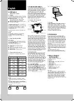
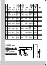
5.2.3.2 Filter Mat Monitoring
The specified filter mat has large pores and filters
coarse dust and lint from the air. Oil condensate is
partially separated out. Fine dust is drawn through
the filter mat and the external circuit of the unit
due to the high suction power of the fan. It does
not have any damaging effect on the function of
the unit.
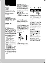
Fig. 5.3
Filter Mat Replacement
Function of the Filter Mat Monitor:
The filter mat is monitored for soiling by meas-
uring the temperature difference in the external
circulation of the cooling unit. In the event of any
filter mat soiling, the temperature difference will
increase. The setpoint value of the temperature
difference in the external circulation is adapted to
various air conditioner operating conditions. This
eliminates the need for subsequent adjustment of
the setpoint value for different operating points of
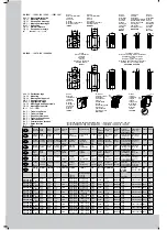
the unit. (For the setting of the filter mat replace-
ment see table 5.1 and fig. 5.1).
5.2.3.3 Door Limit Switch S 2
(supplied by costumer)
Where a door limit switch is used and the enclo-
sure door is open (contact is closed when door is
open), the cooling unit (fans and condenser) will
switch off after approx. 10 s, thereby avoiding an
increase in condensation while the door is open.
To avoid cyclic operation, switch-on of condenser
and external fan is delayed by about 3 minutes
after the door has been closed. The internal fan
will start up immediately on closure of the door.
Connection is made at the terminal strip X10, ter-
minals 1 and 2. The extra low voltage is supplied
by the internal power pack, current is approx.
30 mA DC (no extra low safety voltage). Connect
the door limit switch free from potential only, no
external voltage! The display will flash during the
door delay time. The system message “1010” is
transmitted via the PLC interface.
5.2.3.4 PLC Interface X2 (Option)
The interface is used for the transmission of the
actual internal temperature of the enclosure and
any system messages of the cooling unit to the
PLC. The transmitted information can be dis-
played by means of the output facilities (e.g.
plain text display) which are connected to the
PLC, or by means of the serial interface to a
higher order computer.
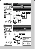
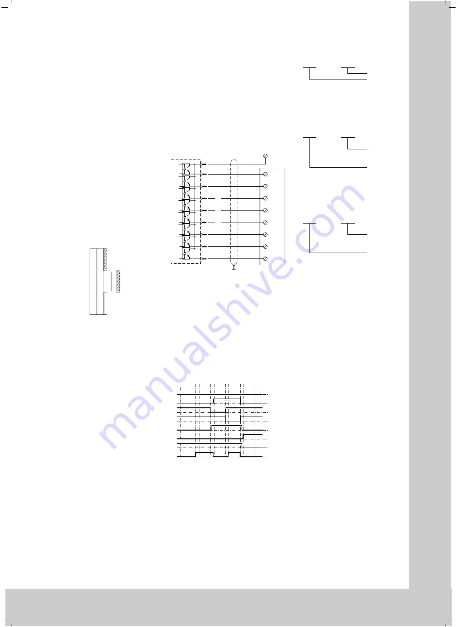
Construction of the PLC interface:
The construction is potential separated via opto-
coupler (wiring diagram fig. 5.4). Connection is
made by the customer to the 15-pin socket on the
control board (fig. 5.4) to the PLC input card.
Attention!
The electrical signals at the interface are of an
extra-low voltage (not extra-low safety voltages
according to EN 60 335).
Fig. 5.4
PLC Interface
Max. loading of the outputs:
30 V/10 mA, direct current
Connection: screened 15-core control cable
The possibility exists to access this information
over the PLC interface (level 8, table 5.1 or
fig. 5.1).
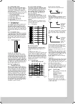
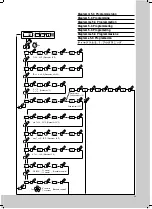
a) Standard mode (Level 8 = “0”)
Communication of the enclosure internal tempera-
ture and of the fault messages is made succes-
sively in 2 s cycle. Since this is an 8-bit parallel
transmission, input signals should not be accept-
ed as valid in the PLC until they have been pres-
ent for 0.5 s. This ensures that no invalid input in-
formation will be evaluated in the event of signal
changes at the inputs.
Fig. 5.5
PLC Interface X2
Pulse/time diagram (example)
9
1
E x.0
2
E x.1
e.g.
+ 24 V
3
E x.2
4
E x.3
5
E x.4
6
E x.5
7
E x.6
8
E x.7
PLC input card
Customer’s supply
15-pin. Sub-D
Cooling unit control card
2 sec.
2
7
6
5
4
3
2
1
0
8
7
6
5
4
3
2
1
0.5
2
0.5
2
0.5
2
0.5
X2
Sub-D plug
Pin
Temperature
32 °C 33 °C
5 Fault 6
store cancel
Temperature
34 °C
Bit
Enclosure internal temperature:
Transmission with 2 digits in BCD format:
System messages:
The system messages are transferred by means
of identification (4 bit) and a fault number
(1 digit BCD). The identification is structured as
follows:
In the event of a fault XXXX (BCD), the identifica-
tion is transmitted cyclically. This information
can be used to store the fault message in the
PLC.
This identification is transferred once, as soon
as the fault with the number XXXX/BCD has
been rectified. This information can be used to
delete the fault message in the PLC.
Evaluation of the interface signals in the PLC:
Messages:
If bit 1 and bit 3 of the input byte have a 1 signal,
the transmitted information is a system mes-
sage. In this case, the meaning of bit 0 is either
the information “store fault message” (bit 0 = 0)
or “cancel fault message” (bit 0 = 1).
Bit 4 to 7 represent the appropriate message
number (BCD).
Temperature:
If the AND operation of bit 1 and bit 3 is not fulfil-
led, the input information represents the actual
internal temperature of the enclosure. In this
case, both BCD digits have valid values (< = 9).
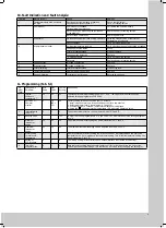
b) Parallel fault codes (Level 8 = “1”).
This can be accessed as follows:
Every one of the eight outputs stands for a cer-
tain system message (see below). It is not pos-
sible to display the internal temperature at the
same time as the system messages.
Output/
System Message
Bit
0
Max. enclosure internal temperature
1
Filter mat soiled
2
Enclosure door is open
3
High-pressure monitor
4
Evaporator
5
Current monitor, compressor
6
Current monitor, internal fan
7
Current monitor, external fan
Because these fault codes are transmitted
through an optocoupler, they can be switched to
a parallel transmission.
Bit 7
ZZZZ
EEEE
Units
Tens
0
Fault number
1 to 8
(see list)
Bit 7
XXXX
1010
Identification
0
“Store fault
message”
Fault number
1 to 8
(see list)
Bit 7
XXXX
1011
Identification
0
“Store fault
message”


