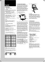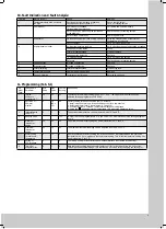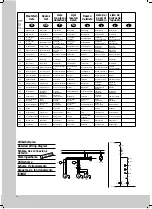
Fig. 7.3
Condensate Discharge
7.4 General
Storage temperature: The cooling units must not
be subjected to temperatures above + 70
°
C
during storage. Transport attitude: The cooling
units must always be transported upright. Waste
disposal: The closed cooling circuit contains cool-
ant and oil which must be correctly disposed of
for the protection of the environment. The disposal
can be carried out at Rittal-Werk.
Technical modifications reserved.
8. Maintenance
As a maintenance-free, hermetically sealed
system, the cooling circuit has been filled in the
factory with the required amount of coolant, and
tested for leaks and subjected to a function trial
run. The installed maintenance-free fans use bull
bearings, they are protected against moisture and
dust, and are fitted with a temperature monitor.
The life expectancy is at least 30,000 operating
hours. The cooling unit is thus largely mainte-
nance-free.
All that may be required from time is that the com-
ponents of the external air circuit are cleaned by
compressed air. The use of a filter mat is recom-
mended only if large particles of lint are present in
the air, so that blockage of the condenser is pre-
vented.
(Filter mat replacement, fig 5.3)
Caution: Prior to any maintenance work, the
power to the cooling unit must be disconnected.
9. Scope of Supply
and Guarantee
1 cooling unit, ready for connection
8 setscrews M8 x 30
8 nuts M8
8 washers A 8.4
1 set of mounting and operating instructions
1 drilling template
1 sealing tape 10 x 8
1 sealing tape 10 x 4
4 (6) self-tapping screws B 4.8 x 13
4 (6) clamps
1 transparent hose 12 x 2 x 100
1 eyebolt (only with SK 3298. . . . /
3279.100 / 3260.500)
Guarantee:
This unit is covered by a 1-year guarantee from
the date of supply, subject to correct usage.
Within this period, the returned unit will be repair-
ed in the factory or replaced free of charge.
The cooling unit is to be used for the cooling of
enclosures only. If it is connected or handled
improperly the manufacturer’s guarantee does
not apply and in this case we are not liable for any
damage caused.
12 x 2 x 100
6. BUS System
(Model No. SK 3124.000)
6.1 General
The BUS system allows a maximum of 7 cooling
units to be interconnected. As a result, the follow-
ing functions are available to the operator:
v
Parallel unit control
(the cooling units in the network can be
simultaneously switched on and off).
v
Parallel door status messages (“door open”).
v
Collective fault message.
The data exchange is carried out using cables
(shielded two-wire leads).
All units are assigned an address. This address
also includes the ID for “Master” or “Slave”.
The BUS system cannot be used to link the
cooling units to a PC.
The PLC interface is switched to parallel error
encoding.
NOTE
The following restrictions must be heeded:
only 6 outputs (0 to 5) are available;
outputs 5, 6 and 7 are routed in parallel to
output 5.
6.2 Notes Regarding Installation
ATTENTION!
The electrical signals at the interface are of an
extra-low voltage (not extra-low safety voltages
according to EN 60 335).
Always heed the following notes!
v
De-energise the cooling units to be
connected.
v
Ensure proper electrical insulation.
v
Make sure the cables are not laid in parallel
to power lines.
v
Make sure that the lines are short.
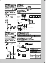
6.3 Programming the Cooling Unit
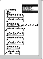
See diagram 5.1 for details on programming.
IDs:
NOTE
Only one unit may be configured as master;
the address ID must match the number of slave
units.
The individual slave units must have different
addresses; the addresses must be in ascending
order (without gaps in between).
Example:
1 master cooling unit with 2 slave cooling units
Master cooling unit
Slave cooling unit
00
Basic state
00
Basic state
01
Master
with 1 slave
11
Slave
with address 1
02
Master
with 2 slaves
12
Slave
with address 2
03
Master
with 3 slaves
13
Slave
with address 3
04
Master
with 4 slaves
14
Slave
with address 4
05
Master
with 5 slaves
15
Slave
with address 5
06
Master
with 6 slaves
16
Slave
with address 6
Master
02
Slave
11
Slave
12
7. Technical Information
The cooling unit (compression refrigeration unit)
consists of four main components: the coolant
compressor, evaporator, condenser, and the con-
trol or expansion valve, which are connected by
suitable pipework. This circuit is filled with a
readily boiling substance, the coolant. The
R134 a (CH
2
FC
3
) coolant is free from chlorine. It
has an ozone destroying potential (ODP) of 0 and
is therefore environmentally friendly. A filter dryer
which is integrated in the hermetically sealed
cooling circuit, provides effective protection
against moisture, acid, dirt particles, and foreign
bodies within the cooling circuit.
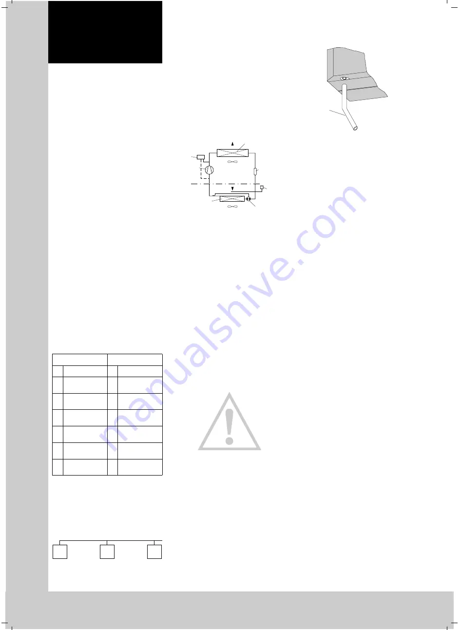
7.1 Operation of the Cooling Unit
Fig. 7.1
Cooling Circuit
When a coolant compressor is put into operation,
the coolant vapour evaporates from the evapora-
tor. The heat required for the evaporation of the
coolant is drawn from the evaporator environment
(internal circuit of the enclosure), causing it to
cool down. The heat fed to the coolant in the
evaporator is its environment (assisted by fans),
making the coolant once more liquid due to the
condensation which takes place. In the thermo-
statically controlled expansion valve, the liquid
coolant is reduced to the particular evaporator
pressure required. The cooling which occurs due
to the reduction of pressure, releases the heat
from the liquid, which evaporates part of the cool-
ant flow. The mixture of cold liquid and throttle
vapour is returned to the evaporator. The cooling
cycle is thus completed, the aforementioned pro-
cess of the heat transfer starts afresh.
7.2 Safety Equipment
The cooling circuit of the cooling unit embodies
a component tested high-pressure monitor to
VBG 20.7.1 which is set to maximum operating
pressure and operates via an automatic reset
device at recurring pressure drop. Temperature
and low-pressure monitoring will prevent the eva-
porator from icing up. If there is a risk of icing up,
the condenser is switched off and automatically
switched on again at higher temperatures.
The coolant compressor and the fans are equip-
ped with thermal winding protection against
excess current and excess temperature.
7.3 Condensate Discharge
Condensate which may form on the evaporator
(under high air humidity, low enclosure tempera-
tures) is discharged through a hose at the eva-
porator partition, at the bottom of the unit. A
connection through the condensate support piece
is used to make this selection (see fig. 7.3, take off
the louvred grille if necessary). Blockage of con-
densate must be avoided.
Fan 2
Fan 1
Pressostat
Compressor
Evaporator
External circuit
Internal circuit
Expansion valve
Thermostat
Filter
dryer
Liquefier
English
8


