

34
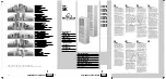
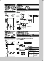
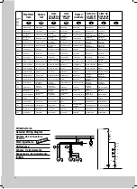
Anschlußschema
Microcontroller
A1
= Leistungsplatine
A2
= Anzeigeterminal
B1
= Temperaturfühler Innentemperatur
B2
= Temperaturfühler Vereisungsschutz
B3
= Temperaturfühler außen 1
B4
= Temperaturfühler außen 2
C1-C4 = Betriebskondensatoren
F1
= Thermostat
F2
= Pressostat
K1
= Relais Sammelstörung
M1
= Verdichter
M2
= Verflüssigerventilator
M3
= Verflüssigerventilator
M4
= Verdampferventilator
S2
= Türendschalter (ohne Türendschalter
Klemme 1, 2 offen)
T1
= Transformator
Kundenseitiger Anschluß:
X2
= SPS-Schnittstelle
(Sub-D-Buchse 15pol.)
X10
= Anschlußklemmleiste
X10
= L1, L2/N, PE = Netzanschluß
braun = L1 (Phase)
blau = L2/N (Neutral)
grün/gelb = PE (Erdung)
L1, L2, L3 (SK 3260.500)
X10
= 1, 2 = Türendschalteranschluß
(Kundenbeistellung)
X10
= 3, 4, 5 = Sammelstörmeldung
Aansluitschema
mikro-controller
A1
= Hoofdstroomprint
A2
= Display
B1
= Temperatuursensor interne temp.
B2
= Temperatuursensor ijsvorming
B3
= Temperatuursensor buiten 1
B4
= Temperatuursensor buiten 2
C1-C4 = Motorkondensator
F1
= Termostaat
F2
= Pressostaat
K1
= Relais verzamelstoring
M1
= Kompressor
M2
= Kondensorventilator
M3
= Kondensorventilator
M4
= Verdamperventilator
S2
= Deurschakelaar (zonder deur-
schakelaar klem 1, 2 open)
T1
= Transformator
Elektrische aansluiting door klant:
X2
= PLC-interface
(Sub-D-konnektor 15-polig)
X10
= Klemmenstrook
X10
= L1, L2/N, PE = netaansluiting
bruin = L1 (Fase)
blauw = L2/N (Nul)
groen/geel = PE (Aarde)
L1, L2, L3 (SK 3260.500)
X10
= 1, 2 = aansluiting deurschalkelaar
(door klant te installeren)
X10
= 3, 4, 5 = algemene storingsindikatie
Esquema de conexiones
del microprocesador
A1
= Pletina de potencia
A2
= Pantalla indicadora
B1
= Sonda térmica de la temp. en el
interiore del armario
B2
= Sonda térmica protección
contra congelación
B3
= Sonda térmica exterior 1
B4
= Sonda térmica exterior 2
C1-C4 = Condensador electrolitico de servicio
F1
= Termostato
F2
= Presostato
K1
= Relé de fallo
M1
= Compresor
M2
= Ventilador del condensador
M3
= Ventilador del condensador
M4
= Ventilador del evaporador
S2
= Interruptor de puerta (sin interruptor
final borne 1, 2 abierto)
T1
= Transformador
Connexión por parte del cliente:
X2
= Interfase de la LCP
(base casquillo D-sub 15 pol.)
X10
= Regleta de bornes
X10
= L1, L2/N, PE = Conexión de red
L1, L2, L3 (SK 3260.500)
X10
= 1, 2 = Bornes de conexión del
interruptor final de carrera S 2,
cierre puerta
X10
= 3, 4, 5 = Bornes de conexión
(señal averia)
D
NL
E
Wiring Diagram
Microcontroller
A1
= Power PCB
A2
= Display Terminal
B1
= Temperature sensor, internal temp.
B2
= Temperature sensor, risk of icing
B3
= Temperature sensor, external 1
B4
= Temperature sensor, external 2
C1-C4 = Operating capacitors
F1
= Thermostat
F2
= Pressostat
K1
= Relay collective fault
M1
= Compressor
M2
= Condenser fan
M3
= Condenser fan
M4
= Evaporator fan
S2
= Door limit switch (without door operated
switch terminal 1, 2 open)
T1
= Transformer
Electrical Connection by Customer:
X2
= PLC interface
(Sub-D-socket, 15-pole)
X10
= Terminal strip
X10
= L1, L2/N, PE = Mains connection
brown = L1 (phase)
blue = L2/N (neutral)
green/yellow = PE (ground)
L1, L2, L3 (SK 3260.500)
X10
= 1, 2 = Door operated switch
connection (supplied by customer)
X10
= 3, 4, 5 = Collective fault message
Anslutningsschema
microcontroller
A1
= Drivkort
A2
= Display terminal
B1
= Temperaturgivare innertemperatur
B2
= Temperaturgivare nedisningsrisk
B3
= Temperaturgivare yttre 1
B4
= Temperaturgivare yttre 2
C1-C4 = Startkondensator
F1
= Termostat
F2
= Pressostat
K1
= Samlingsrelä felsignaler
M1
= Kompressor
M2
= Kondensorfläkt
M3
= Kondensorfläkt
M4
= Förångarfläkt
S2
= Dörrströmbrytare (utan dörrström-
brytarklämma 1, 2 öppna)
T1
= Transformator
Ansluts av kund:
X2
= PLC-ingång
(D-Sub-uttrag 15-pol)
X10
= kopplingsplint
X10
= L1, L2/N, PE = nätanslutning
brun = L1 (Fas)
blå = L2/N (Nolla)
grön/gul = PE (Jord)
L1, L2, L3 (SK 3260.500)
X10
1, 2 = anslutning dörrkontakt
(måste beställas separat)
X10
= 3, 4, 5 = samlingsstörnings-anslutning
GB
S
J
Schéma électrique
microprocesseur
A1
= Platine de puissance
A2
= Display Terminal
B1
= Sonde te température,
température intérieure
B2
= Temp. sensor danger de givrage
B3
= Sonde de température extérieure 1
B4
= Sonde de température extérieure 2
C1-C4 = Condensateur de régime
F1
= Régulateur de température
F2
= Pressostat
K1
= Relais pertubations
M1
= Compresseur
M2
= Ventilateur du condenseur
M3
= Ventilateur du condenseur
M4
= Ventilateur de l’évaporateur
S2
= Interrupteur de porte (sans contacteur
les bornes 1, 2 sont ouverttes)
T1
= Transformer
Electrical Connection by Customer:
X2
= Interface SPS
(douille Sub-D 15 pôles)
X10
= Borne plate de raccordement
X10
= L1, L2/N, PE = Raccordement au résau
brun = L1 (phase)
bleu = L2/N (neutre)
vert/jaune = PE (mise à la terre)
L1, L2, L3 (SK 3260.500)
X10
= 1, 2 = Raccordement de l’interrupteur
de porte (à monter par le client)
X10
= 3, 4, 5 = Connexion de la signalisation
de défaut
Schema allacciamenti
microcontrollore
A1
= Scheda di potenza
A2
= Display terminale
B1
= Sonda temperatura interna
B2
= Sonda temperatura,
pericolo di formazione di ghiaccio
B3
= Sonda temperature esterna 1
B4
= Sonda temperature esterna 2
C1-C4 = Condensatore d’esercizio
F1
= Termostato
F2
= Pressostato
K1
= Relè segnalatore guasti
M1
= Compressore
M2
= Ventilatore del condensatore
M3
= Ventilatore del condensatore
M4
= Ventilatore dell’evaporatore
S2
= Interruttore della portina (senza inter-
ruttore i morsetti 1, 2 sono aperti)
T1
= Transformatore
Connessioni elettriche a cure del cliente:
X2
= Interfaccia PLC
(presa 15 poli)
X10
= Morsettiera d’allacciamento
X10
= L1, L2/N, PE = Allacciamento rete
marrone = L1 (fase)
azzurro = L2/N (neutro)
verde/giallo = PE (terra)
L1, L2, L3 (SK 3260.500)
X10
= 1, 2 = Allacciamento interruttore fine
corsa della portina (forn. dal cliente)
X10
= 3, 4, 5 = Segnalatore comune disturbi
F
I


