
2
5
4
3
2
1
L1
B3
B2
B1
PE
21
22
B4
2
2
2
6
8
TEST
ENTER
°F
°C
15
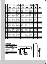
Technische Daten
siehe Typenschild
L2 L3
4
5
gg
1
2
3
1 2 3
5
4
6
6
4 5
3
2
1
1 2 3
5
4
6
1
2
K1
X10
A1
S2
A2
X2
F2
L3
L2
L1
F10
M1
F20
M2
M4
F40
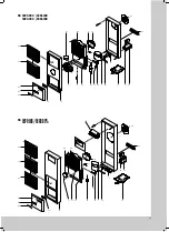
SK 3260.500
V
W
U
3
M
M
3
P
Technical data
see name plate
SK 3290.500 without/ohne C3
SK 3290.500 without/ohne C3
M2
K1
SK 3293.500
SK 3298.500
SK 3298.500
A1
S2
C2
C4
M4
M3
C2
C1
M2
SK 3293.500 without/ohne C1
SK 3298.500
SK 3298.500
A2
X2
M1
F2
2
5
4
3
2
1
L1
PE
21
22
B3
B2
B1
B4
2
2
2
6
8
°C
TEST
ENTER
°F
15
14
11
10
13
12
L1
PE
L2
N
2
1
3
5
4
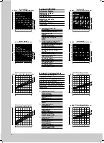
Technical data
see name plate
Technische Daten
siehe Typenschild
P
M
1~
1~
M
M
1~
1~
M
L2
N
X10
M
1~
M
1~
M
1~
L/L'
N
L
N
ϑ
>
P>
N
PE
L
Technische Daten
siehe Typenschild
* nur bei Trafoeinbau
P<
L'
*
F2
M1
M2
M4
C1
F1
C4
F3
C2
T1
Techn. data
see type-plate
F2
M1
C1
F1
C4
L/L'
N
L
N
F3
C2
N
PE
L
L'
T1
M
M2
1~
M4
M
1~
M
1~
F3
F3
ϑ
>
P>
s. Typenschild
Techn. Daten
* nur bei Trafoeinbau,
*
only for transformer
*
see type-plate
Techn. data
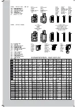
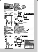
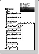
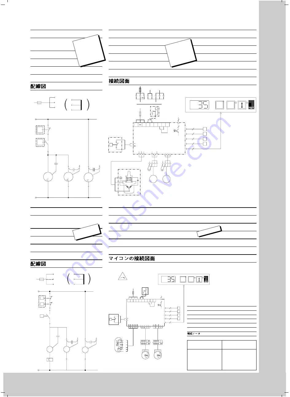
Kontaktdaten K1
Contact Data K1
Caracteristiques des contacts K1
Kontaktgegevens K1
Kontaktdata K1
Caratteristiche dei contatti K1
Características del contacto K1
AC
cosf = 1
DC
L/R = 40 ms
I max.= 5 A
U max.= 230 V
I min. = 10 mA
U max.
= 100 V
!
I max.= 200 mA
U max.= 20 V
!
I max.= 5 A
K 1
35
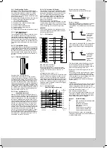
Wirkschaltplan
Detailed Wiring Diagram
Schéma des con-
nexions détaillé
Werkingsschema
Driftschema
Schema d’allacciamento
Esquema de funcionamiento
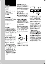
Anschlußschema
Wiring Diagram
Schéma électrique
Aansluitschema
Anslutningsschema
Schema allacciamenti
Esquema de conexiones
Wirkschaltplan
Detailed Wiring Diagram
Schéma des connexions
détaillé
Werkingsschema
Driftschema
Schema d’allacciamento
Esquema de funcionamiento
SK 3293.100
SK 3293.140
SK 3281.100
SK 3393.100
SK 3393.140
SK 3381.100
SK 3298.100
SK 3279.100
Anschlußschema Microcontroller
Wiring Diagram Microcontroller
Schéma électrique microprocesseur
Aansluitschema mikro-controller
Anslutningsschema microcontroller
Schema allacciamenti microcontrollore
Esquema de conexiones del microprocesador
SK 3260.500
SK 3293.500
SK 3293.540
SK 3393.500
SK 3393.540
SK 3398.500


