9
EN
Date: 01-05-2015
Installation Guide
33130328
Description
Technical specifications
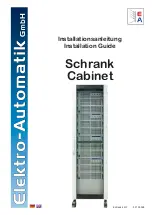
Type: Rittal TS8 42U
Dim (WxHxD): 600 mm x approx. 2000 mm x 800 mm
Model: rear and front doors, on wheels
AC input connection: L+N+PE
AC input voltage: 115/230 V AC
Ambient temperature: 5....40 °C
Humidity: <80%, non-condensing
Weight: ~390 kg
DC input: 80 V / 2400 A / 21600 W
Feature overview
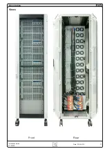
• Wheels (4 pcs. of which 2 can be locked)
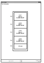
• Equipped with 4x EL 9080-600 HP of 9U height each
• Master-Slave wiring on analog interfaces
Installation
Cabinet
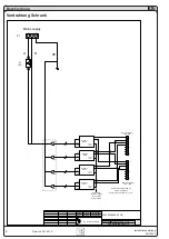
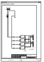
The AC input connection is done using screw terminals which
are accessible on the rear side in the bottom right corner and
labelled L1, N, PE. The input is fused with a 16A circuit breaker
(F1), so the cross section of the AC supply cables has to be
selected accordingly.
For additional safety, every unit has a fusible, which is accessible
on the rear of the units in a fuse holder and labelled with the fuse
value (see sticker).
Units
The electronic load units are delivered separately and have to be
inserted after the cabinet has been installed in the target location.
The devices are of same model, so they can be placed anywhere.
After inserting and mounting the units, you need to connect:
• AC supply (IEC cable)
• DC input (cables, red/blue, 4 cable ends per units)
• Master-slave wiring on analog interface, if required
DC input
The four units are connected in parallel via cables on two copper
bars for DC plus and DC minus. The DC terminal is not protected
against physical contact.
The DC input copper bars for voltage/current source connection
are down below on the rear and are horizontally mounted.
DC source are connected via cables (or similar) with proper cross
section (according to local standards) on the DC input copper
bars, using M12 nuts and bolts.
Attention!
Always connect only DC sources and only with cor-
rect polarity!
The electronic loads do not have protection against
false polarity and can even be damaged in switched-
off state.
Analog interface
The analog interface of all units in the cabinet can be used
with the preconfigured wiring to have a current driven mas
-
ter-slave system. The topmost unit is defined as master
unit. All units are labelled on the front side.
The slave units are in permanent remote control (indicated
as „External mode“ in display) as long as the master-slave
wiring on the analog interface is plugged. In case you need
to access a unit separately or take over remote control via
digital interface, it is sufficient to remove the plug from the
analog interface.
When re-configuring the cabinet or in case of removing an
unit for repair, the setup of master and slave units should be
kept and the master-slave wiring re-connected as before.
Operation
Handling of the electronic loads
See separate manual of EL 9000 HP 7200W.
General
For general information about remote control of the electronic
loads via analog or digital interface refer to various available docu-
mentation (device manual, interface manual, programming guide).
Remote control
Note
It is generally possible to remotely control all units at once
or just single units.
With the given situation, remote control is only intended for
the master unit, because it controls the slave units. These can
only be monitored via digital interface, unless master-slave is
disconnected.
The software Easyload Lite, as supplied from the manufacturer
of the electronic loads, is designed to control only one unit. This
should be the master unit. In case all four units of a cabinet are
networked, the software will detect four identical units and the
particular master can only be distinguished from the slaves by its
IP or the serial number. Thus Easyload Lite is only of limited use.
In order to control the whole cabinet as one big system, it requires
to create a custom software, which either controls only the master
unit and translates all values accordingly before sending it to
the device. Because of the analog master-slave wiring, there is
no digital communication between the units and so the master
unit has to be considered as single device concerning values to
send/receive.
Alternatively and at least when monitoring the units regarding
set values, the single units could be read and totalled, so the
resulting actuals are more accurate than just reading the master
and multiplying current and power by the number of units.

