INSTALLATION
Installation Instructions for SIS Bus Bar Systems A2MS001EN revision R05
61 / 130
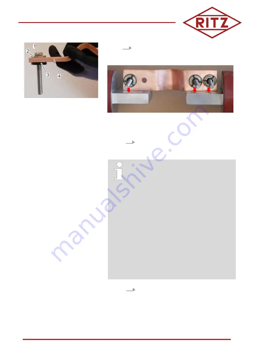
Fig. 45: Flexible connector (example
view)
1 Bolt
2 Washer
3 Al elast contact disc
4 Flexible connector
5.
Check that the Al elast contact discs are in the
correct position (Fig. 45).
Fig. 46: Flexible connector and connections for the bus bars
6.
In this example: Insert two flexible connectors with
the bolts through the drilled holes in the flange
connections of the bus bars from above (Fig. 46).
For this example, make sure one hole, towards the
center of the flexible connector, on the side of the
connector from which the contact tube will be pushed,
remains empty for the contact springs (Fig. 46), and is
similar on both flexible connectors.
The number of flexible connectors needed is indicated
in the drawings specific to the respective project. The
normal procedure of installing the flexible connectors
is to assemble one side of the connector(s), complete
with bolts, washers, Al elast contact discs (as needed),
and contact springs with associated hardware, and
then to insert onto the flange connections of the bus
bar, with the contact spring mounted on the side of the
flexible contacts from which the contact sleeve will be
slid (this will be made clear later). However, for the
purpose of emphasizing the proper installation of the
contact springs and associated hardware, the contact
springs have been highlighted separately in these
instructions.
Be aware that at the end every hole, including the hole
which is left empty in the step showing in Fig. 46, has
an Al elast contact disc and associated hardware
assembled.
7.
Prepare the flexible connectors for the other side
(underside of the bolted connection) with Al elast
contact discs (see steps 3 and 4).


