RTC Series
RTC Installation Guide
01A.04
7
1
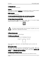
Analog video out
It is an analog video output port.
2
Reset
Reset switch is used for restarting or resetting the camera as Factory Default
(FD). Refer to the section “5.3.Reset” for more specific information.
3
USB connector
Insert a USB storage device
4
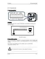
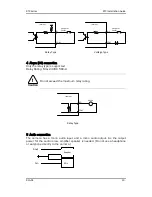
9 pin terminal block for D/I, D/O, audio, and serial communication
Refer to the section “
4.1.Connectors
” for more specific information.
5
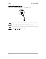
Power Adaptor Connector (DC 12V)
The camera needs a DC12V for power supply. Refer to the section “
Power
Adapter Connector (DC 12V)
” for more specific information.
The device is polarity sensitive. Incorrect power connection may cause
malfunction or damage to the IP device
6
Micro SD Card socket
It is a memory card slot for local storage.
7
LAN Connector (Ethernet)
This is a RJ45 LAN connector for 10/100 Base-T Ethernet.
When the device is powered on, the orange LED lights up first, and then the
green LED.
LED operation setting:
Both LEDs are off when the device is disconnected from a network. When it is
connected, the orange LED turns into solid light, whereas the green LED
continues to blink. To change the setting, refer to the section
4.5.12. LED
Setting
of the
NVC Web Page User’s Manual.
8
Adaptor for mounting the camera
Mounting adaptor is provided to mount the camera on a bracket or tripod.
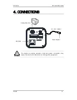
Orange LED
Green LED
+ -
Caution
!

