
Instruction Manual IM‐116
CUSTOMER'S INFORMATION BOX
CONTENTS ARE INDEPENDENT OF RIVERHAWK DOCUMENT CONTROL
215 Clinton Road
New Hartford, NY 13413
Tel: +1 315 768 4855
Fax: +1 315 768 4941
Email: info@riverhawk.com
REV
373A4028
GE DRAWING NUMBER
Revision H
Page 13 of 29
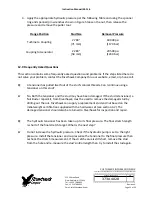
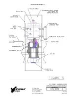
If the puller tool is not free to rotate when the puller screw is tight, then either. (1) The
tensioner is damaged, or. (2) The stud is not properly positioned in the flange and the nuts
must repositioned. This can be done as follows.
1.
Slightly loosen the puller screw
2.
Back the nut opposite the puller tool off about 1/2 turn
3.
Tighten the puller screw side nut to take up the slack.
4.
Retighten the puller screw per above and check for looseness of tool
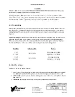
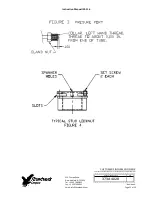
CAUTION
Personal injury and equipment damage can occur if the puller screw is not securely engaged
with the tapered thread of the stud. Proper engagement is achieved when the puller screw is
tight in the stud and the Tensioner Assembly is free to rotate.
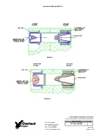
9.0 Stud Pulling and Tensioning
The studs will be tensioned in two steps, at approximately 50% pressure and at final pressure.
Follow the tensioning sequence for each flange joint as defined on the data sheets found at the
end of this manual
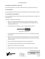
Note:
Before threading the puller screw into the stud, carefully check the cleanliness of both
the stud's and the puller screw's conical threads. Apply a light coat of clean turbine oil or a
spray lubricant to the puller screw. Do not use “Never Seize” on the conical threads. This
procedure will ease assembly and assure positive mating of the threads before tightening.
WARNING
The safety cage MUST be in place and hands kept out of designated areas at all times when the
puller tool is pressurized otherwise personal injury can occur.
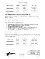
9.1 Tensioning at 50% pressure
After the tensioner is properly installed apply hydraulic pressure to the tool. Bring the pressure
to the 50% level in accordance with the following table.


