background image

Instruction Manual IM‐116 


CUSTOMER'S INFORMATION BOX

CONTENTS ARE INDEPENDENT OF RIVERHAWK DOCUMENT CONTROL


215 Clinton Road 

New Hartford, NY 13413 

Tel: +1 315 768 4855 

Fax: +1 315 768 4941 

Email: info@riverhawk.com


REV

373A4028

GE DRAWING NUMBER


Revision H 

 Page 29 of 29


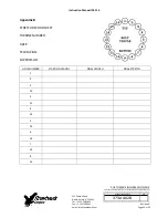
Appendix B 


STRETCH RECORD SHEET


TURBINE NUMBER: 


DATE: 


TECHNICIAN: 


SUPERVISOR: 


HOLE NUMBER 

STARTING LENGTH 

FINAL LENGTH 

FINAL STRETCH 


10 


11 


12 


13 


14 


15 


16 


Summary of Contents for IM-116

Page 1: ...INDEPENDENT OF RIVERHAWK DOCUMENT CONTROL ISSUED THIS DOCUMENT SHALL BE REVISED IN ITS ENTIRETY ALL SHEETS OF THIS DOCUMENT ARE THE SAME REVISION LEVEL AS INDICATED IN THIS VENDOR SUPPLIED DRAWING APPLIQUE REV 373A4028 GE DRAWING NUMBER VENDOR SUPPLIED THIS DOCUMENT IS FILED UNDER THE GE DRAWING NUMBER GE NOT TO REVISE GE REVISION LEVEL IS SHOWN ON THIS APPLIQUE GE SIGNATURES CHECKED The Riverhawk...

Page 2: ...utions and Safety Warnings 3 2 0 Scope 4 3 0 Quick Check List 4 4 0 General Preparations 7 5 0 Hardware Set Preparations 8 6 0 Stud and Nut Assembly 10 7 0 Assembly of Hydraulic Tensioner Equipment 10 8 0 Assembly of Tensioner on Stud 12 9 0 Stud Pulling and Tensioning 13 10 0 Thread Locking 15 11 0 Stud Nut Removal 15 12 0 Frequent Asked Questions 16 13 0 Revision History 18 Appendix A1 EC Declar...

Page 3: ...s free to rotate WARNING Risk of high pressure hydraulic fluid injection Riverhawk tools operate under high pressure Thoroughly inspect all hoses and connections for damage or leaks prior to using this equipment WARNING The proper personal protective equipment must be worn at all times Riverhawk recommends at a minimum safety glasses long sleeve shirt hard hat heavy work gloves and steel toe shoes...

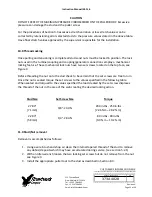
Page 4: ...e This document describes the procedure to be used to install studs and nuts supplied by Riverhawk Company in the flanges at the turbine coupling and coupling generator connections This hardware is depicted on the following drawings These drawings as well as the tooling drawings form a part of this manual HF 0813 3 0 Quick Checklist The following checklist is intended as a summary of the steps nee...

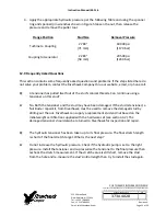
Page 5: ...asurement VERY IMPORTANT Tensioning Bolt installation Match the tensioner setup to the flange joint Apply a light coat of clean turbine oil or spray lubricant to the puller screw DO NOT USE NEVER SEIZE ON THE CONICAL THREADS Slide spanner ring over the puller screw Mount the tensioner on the stud in flange Install spanner ring onto nut Insert 1 2 hex Allen wrench into the back side of the stud Tig...

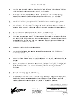
Page 6: ...s set screws Detensioning Stud removal Loosen nuts set screws Inspect and clean studs conical threads Do not continue until ALL debris is removed from the threads Do not try to use the tensioner to remove a damaged stud Apply a light coat of clean turbine oil or spray lubricant to the puller screw DO NOT USE NEVER SEIZE ON THE CONICAL THREADS Slide spanner ring over the puller screw Mount the tens...

Page 7: ...nge The nut is then reseated into position on the flange by turning a nut driver by hand When the nut is tight against the flange the pressure in the tensioner is released leaving the stud loaded to its predetermined value 4 1 Machine Preparation The flange to be tensioned must be fully closed prior to positioning of studs in the flanges There must be provision to turn the shafts of the turbine an...

Page 8: ...mpact wrench A set of Allen Wrenches 3 4 Breaker Bar 9 to 10 micrometer or caliper 10 to 11 micrometer or caliper 4 5 Special Tools Hydraulic Tensioner Kit HT 0814 Hydraulic Tensioner Hydraulic Pump Kit AP 0532 Air Operated Hydraulic Pump recommended reference GE 359B2502 MP 0130 Manual Hand Operated Hydraulic Pump reference GE 359B2506 5 0 Hardware Set Preparations 5 1 Nut Preparation For new ins...

Page 9: ...low these steps 1 Blow out the threads with compressed air to remove loose debris and dry conical threads Do not apply a solvent or other cleaning solution to the threads as this may chemically attack the stud 2 Use Stud Cleaning Kit GT 4253 or a similar 1 diameter Brass power brush Picture of Brass Power Brush 3 Insert the brush into an electric drill and set drill to run in a counterclockwise di...

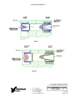
Page 10: ...n the supplied charts Do not allow the measuring instruments to set in the sun 6 0 Stud and Nut Assembly Refer to hardware assembly drawing HF 0813 listed in Section 2 0 of this manual 1 Assemble cylindrical nut to the tapered thread end Pull End of the stud 2 Slide the stud and cylindrical nut assembly into the flange as shown in Figures 1 2 and install the other nut on the backside 3 Adjust the ...

Page 11: ...ic oil The pump reservoir cap is sealed for shipment To use turn cap to the vent position To prevent oil spillage close cap when not in use during storage and shipment Lost oil should be replaced with Enerpac Hydraulic Oil ISO 32 Mineral Oil may be substituted if necessary 7 3 Bleeding Hydraulic System Follow the tensioner assembly instructions of Section 8 0 TO AVOID FAILURE ENSURE SAFETY AND PRO...

Page 12: ...following features which should make stud tensioning safe and easy The safety cage is integral bolted to the puller tool The hydraulic piston is spring loaded to retract The puller screw is a 2 piece design which requires that the operator tighten the puller screw into the stud Assembly sequence is as follows 1 Open the hydraulic return valve on the hand pump to allow hydraulic fluid to be pushed ...

Page 13: ...gagement is achieved when the puller screw is tight in the stud and the Tensioner Assembly is free to rotate 9 0 Stud Pulling and Tensioning The studs will be tensioned in two steps at approximately 50 pressure and at final pressure Follow the tensioning sequence for each flange joint as defined on the data sheets found at the end of this manual Note Before threading the puller screw into the stud...

Page 14: ...ler tool removal is to accomplished as follows 1 Release the puller tool pressure by opening the valve on the pump Leave the valve open This is automatic on the air operated hydraulic pump 2 Unscrew the puller screw using a wrench 3 Tapping the wrench with a hammer may be necessary to loosen the puller screw 4 Move the tool to the next stud nut assembly to be tensioned following the sequence patte...

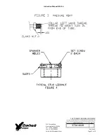
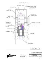
Page 15: ...onnections employ a mechanical locking feature These mechanical lock nuts have two set screws located on the top face see Figure 4 Before threading the nut onto the stud check to be certain that the set screws are free to turn Once the nut is seated torque the set screws to the values specified in the following table When seated and torqued to the values specified the load created by the set screw...

Page 16: ...e call Q A tensioner has pulled itself out of the stud s conical threads Can I continue using a tensioner on this stud A No Both the tensioner and the stud may have been damaged If the stud is tensioned a Nut Buster repair kit from Riverhawk must be used to remove the damaged stud by drilling out the nut Riverhawk can supply a replacement stud and nut based on the initial weight certification supp...

Page 17: ... its final pressure but the nut cannot be loosen A If the nuts cannot be loosened at the final pressure continually increasing the pressure will not help and can be dangerous and in some cases make it harder to remove the nut Check the nut to see if its set screws have been loosened Check for and remove any corrosion around the nut s threads Q How do I clean the conical threads on a stud A The con...

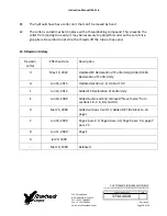
Page 18: ...cessary to adjust this collar with a set of vise grip pliers Be careful to not strip the threads off the tube or hose end 13 0 Revision History Revision Letter Effective Date Description H May 19 2022 Updated EC Declaration of Conformity Added UKCA Declaration of Conformity G Jan 16 2015 Updated sections 1 0 4 3 and 14 0 F Jun 13 2014 Added EC Declaration of Conformity E Jun 10 2009 Added turbine ...

Page 19: ... and applying tension to large bolts that are specifically designed by Riverhawk Company to be tensioned hydraulically All applicable sections of European Directive 2006 42 EC for machinery have been applied and fulfilled in the design and manufacture of the hydraulic pump and bolt tensioning tool described in this manual Reference also ISO 12100 2010 ISO 4413 2010 and ISO 4414 2010 Furthermore th...

Page 20: ...talling and applying tension to large bolts that are specifically designed by Riverhawk Company to be tensioned hydraulically All applicable sections of Supply of Machinery Safety 2008 have been applied and fulfilled in the design and manufacture of the hydraulic pump and bolt tensioning tool described in this manual Reference also ISO 12100 2010 ISO 4413 2010 and ISO 4414 2010 Furthermore this eq...

Page 21: ...ER S INFORMATION BOX CONTENTS ARE INDEPENDENT OF RIVERHAWK DOCUMENT CONTROL 215 Clinton Road New Hartford NY 13413 Tel 1 315 768 4855 Fax 1 315 768 4941 Email info riverhawk com REV 373A4028 GE DRAWING NUMBER Revision H Page 21 of 29 ...

Page 22: ...ER S INFORMATION BOX CONTENTS ARE INDEPENDENT OF RIVERHAWK DOCUMENT CONTROL 215 Clinton Road New Hartford NY 13413 Tel 1 315 768 4855 Fax 1 315 768 4941 Email info riverhawk com REV 373A4028 GE DRAWING NUMBER Revision H Page 22 of 29 ...

Page 23: ...ER S INFORMATION BOX CONTENTS ARE INDEPENDENT OF RIVERHAWK DOCUMENT CONTROL 215 Clinton Road New Hartford NY 13413 Tel 1 315 768 4855 Fax 1 315 768 4941 Email info riverhawk com REV 373A4028 GE DRAWING NUMBER Revision H Page 23 of 29 ...

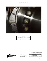
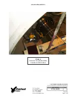
Page 24: ...ENDENT OF RIVERHAWK DOCUMENT CONTROL 215 Clinton Road New Hartford NY 13413 Tel 1 315 768 4855 Fax 1 315 768 4941 Email info riverhawk com REV 373A4028 GE DRAWING NUMBER Revision H Page 24 of 29 Photo 1 Section of 9FA turbine flange with studs in place prior to tensioning ...

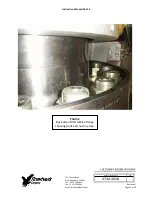
Page 25: ...DEPENDENT OF RIVERHAWK DOCUMENT CONTROL 215 Clinton Road New Hartford NY 13413 Tel 1 315 768 4855 Fax 1 315 768 4941 Email info riverhawk com REV 373A4028 GE DRAWING NUMBER Revision H Page 25 of 29 Photo 2 Back side of 9FA turbine flange showing studs and nuts in place ...

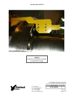
Page 26: ...ARE INDEPENDENT OF RIVERHAWK DOCUMENT CONTROL 215 Clinton Road New Hartford NY 13413 Tel 1 315 768 4855 Fax 1 315 768 4941 Email info riverhawk com REV 373A4028 GE DRAWING NUMBER Revision H Page 26 of 29 Photo 3 Side view of tensioner mounted on 9FA turbine flange ...

Page 27: ...ARE INDEPENDENT OF RIVERHAWK DOCUMENT CONTROL 215 Clinton Road New Hartford NY 13413 Tel 1 315 768 4855 Fax 1 315 768 4941 Email info riverhawk com REV 373A4028 GE DRAWING NUMBER Revision H Page 27 of 29 Photo 4 Tensioner in operation while mounted on 9FA turbine ...

Page 28: ... INDEPENDENT OF RIVERHAWK DOCUMENT CONTROL 215 Clinton Road New Hartford NY 13413 Tel 1 315 768 4855 Fax 1 315 768 4941 Email info riverhawk com REV 373A4028 GE DRAWING NUMBER Revision H Page 28 of 29 Photo 5 View of operator tightening nuts on Fr 9FA turbine flange ...

Page 29: ...ton Road New Hartford NY 13413 Tel 1 315 768 4855 Fax 1 315 768 4941 Email info riverhawk com REV 373A4028 GE DRAWING NUMBER Revision H Page 29 of 29 Appendix B STRETCH RECORD SHEET TURBINE NUMBER DATE TECHNICIAN SUPERVISOR HOLE NUMBER STARTING LENGTH FINAL LENGTH FINAL STRETCH 1 9 2 10 3 11 4 12 5 13 6 14 7 15 8 16 ...

Reviews: