Check for parts online at
www.HuntRiversEdge.com
or call 800-345-6007 M-F 8-5
10
Operator's Manual
BOWMAN XT Ladder Stand
FIGURE
7
FIGURE 8
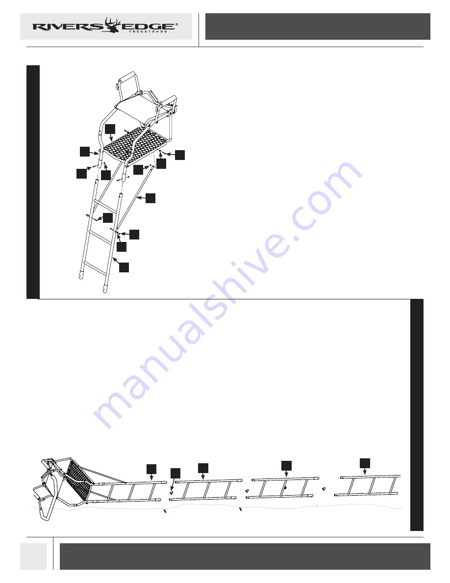
10. Attach one end of both brace supports (16) to rear of
platform (4) using two 1/4-20 X 1-1/2 IN bolts (23), yellow
plastic washers (18) and locknuts (26). SEE FIGURE 7.
11. Attach top ladder section (7) to flared platform rails (5)
using two 1/4-20 X 1-1/2 IN bolts (23) and locknuts (26).
SEE FIGURE 7.
12. Attach other ends of brace supports (16) to top ladder
section (7) using two 1/4-20 X 1-1/2 IN bolts (23), yellow
plastic washers (18) and locknuts (26). SEE FIGURE 7.
7
23
18
26
16
5
26
23
26
18
23
4
ground
13. Ladder sections are assembled on the ground in the
following order: bottom ladder section (10), middle ladder
section with stabilizer slot (9), middle ladder section (8)
and the top ladder section (7) with the treestand top
assembly.Connect all sections together using the six
lockpins (17). SEE FIGURE 8.
7
8
10
17
9
Summary of Contents for BOWMAN XT
Page 6: ......


