Check for parts online at
www.HuntRiversEdge.com
or call 800-450-EDGE (3343) M-F 8-5
23
Operator's Manual
Rivers Edge® One-Man Ladder Stands
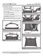
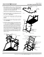
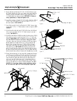
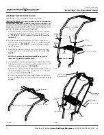
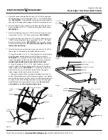
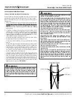
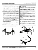
FIGURE 13 -
Install previously removed bolt and locknut
FIGURE 14 -
Tighten front brace bolts and locknuts (4)
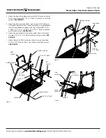
FIGURE 12a -
Front hinged brace in vertical position
FIGURE 12b -
Front hinged brace rotated into locked position
FIGURE 11 -
Insert (2) 1/4-20 x 1-1/4" bolts
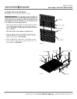
FIGURE 10 -
Remove "locking" bolt and hinge front brace
SEAT ASSEMBLY CONTINUED
e. Remove the factory installed "locking" bolt and locknut from the
front hinged brace (410115), and set aside. Hinge the brace slightly
to aid in assembly.
SEE FIGURE 10.
f. Insert (2) 1/4-20 x 1-1/4" bolts through the front hinged brace and
each side rail, and finger tighten locknuts.
SEE FIGURE 11.
Brace
should remain hinged.
g. Rotate the front hinged brace towards the seat to lock the brace
in position.
SEE FIGURES 12a and 12b.
h. Push down on the front hinged brace and install the previously
removed bolt and locknut.
SEE FIGURE 13.
i. Tighten all (4) bolts and locknuts on the front hinged brace at this
time.
SEE FIGURE 14.
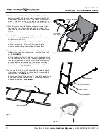
This will tighten up the side rails of the seat
to the braces and square up the entire seat.
NOTE: The rear fixed brace locknuts will need to be removed in
order to attach finished seat and should not be tightened at this
time.
"locking" bolt hole location
Keep brace hinged.
Push front hinged brace
down
firmly
.
bolt
locknut
PUSH DOWN

