Check for parts online at www.HuntRiversEdge.com or call 800-345-6007
7
Operator’s Manual
Landmark
™
600 Blind
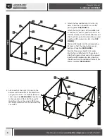
STEP 6A
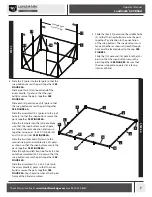
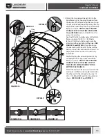
5. Slide the four (19) poles into the middle hubs
(2) so that the snap buttons secure the parts
together. Pay attention to the orientation
of the snap buttons. The snap buttons must
face each other as shown and each through-
hole must be located closer to the top. SEE
FIGURE 5.
Slide the (10) pole and (16) pole into the (30)
parts so that the snap buttons secure the
parts together. SEE FIGURE 5. Be sure that
the door stop plate on pole (16) is facing
interior of blind.
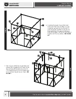
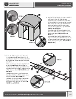
6. Slide the (7) pole into the (6) pole so that the
snap button secures the parts together. SEE
FIGURE 6A.
Slide a roof hub (3) onto each end of the
assembled (6, 7) poles so that the snap
buttons secure the parts together. SEE
FIGURE 6A.
Slide each (4) pole into each (5) pole so that
the snap button secures the parts together.
SEE FIGURE 6A.
Slide the assembled (4, 5) poles into the roof
hubs (3) so that the snap buttons secure the
parts together. SEE FIGURE 6A.
Slide the (34) pole into the (33) pole. Make
sure that the snap buttons on each pole
are facing the same direction and secure
together using one 1/4-20 X 1 IN bolt (52)
and 1/4-20 nut (56). SEE FIGURE 6A.
Slide the two door hubs (9) down to the
second snap pin in assembled (33, 34) poles
as shown so that the snap buttons secure the
parts together. SEE FIGURE 6A.
Slide the right and left front roof hubs (35, 36)
onto the assembled (33, 34) poles so that the
snap buttons secure the parts together. SEE
FIGURE 6A.
Slide the assembled (9, 33, 34, 35, 36) onto
the assembled (4,5) poles so that the snap
buttons secure the parts together. SEE
FIGURE 6A. You should now have the top tier
frame of the blind assembled.
STEP 5
STEP 5
10
30
16
19
2
Through hole
closer t
o top
3
6
7
9
52
4
36
4
5
5
35
33
56
34
10
16
30
2
19
5
4
36
7
3
34
6
9
56
33
5
52
4
35


